
Introduction
A digital display decoder IC is an electronic device that converts one digital format into another. One of the most commonly used types is the Binary Coded Decimal (BCD) to 7-Segment Display Decoder, which converts a 4-bit binary input into signals that can drive a 7-segment display.
Seven-segment displays are widely used to show digits in digital watches, calculators, clocks, measuring instruments, and counters. Both LED and LCD displays use these segments to produce readable numerical values or characters.
However, since digital integrated circuits (like latches or decade counters) output signals in a 4-bit BCD format, a decoder is required to translate these signals into the corresponding seven-segment outputs. This makes the decoder an essential component for visual display systems.
Types of Seven-Segment LED Displays
There are two main types of seven-segment LED displays:
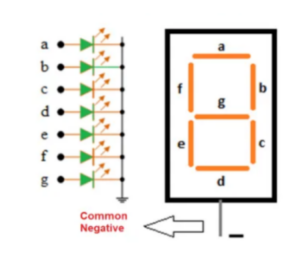
1. Common Cathode Display (CCD)
In a common cathode display, the cathodes of all seven LEDs are connected together and grounded (connected to -Vcc). Each segment’s anode terminal is connected separately to a current source. A segment lights up when a HIGH signal is applied to its anode.
When interfacing a common cathode display with a microcontroller, the anodes of each segment are connected to the microcontroller’s output pins. To turn on a segment, a logic 1 (high) is applied to the corresponding output pin.
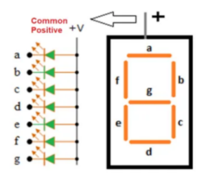
2. Common Anode Display (CAD)
In a common anode display, all the anodes of the LEDs are tied together and connected to +Vcc. Each cathode is connected to the circuit separately. To illuminate a segment, its cathode is grounded (logic 0).
When connecting a common anode display to a microcontroller, the cathodes are linked to the port pins. To activate a particular segment, logic 0 must be applied to its corresponding output pin.
BCD to Seven-Segment Decoder
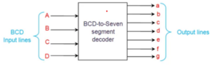
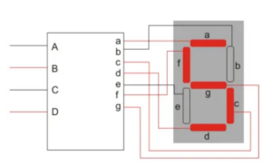
A BCD to seven-segment decoder converts a 4-bit binary-coded decimal (BCD) input into control signals that illuminate the appropriate segments of a 7-segment display to represent decimal digits (0–9).
This circuit typically has four input lines — A, B, C, and D — and seven output lines — a, b, c, d, e, f, and g. The truth table specifies which segments must be turned ON to display a particular decimal digit.
For a common cathode configuration, a logic 1 (high) turns ON a segment, whereas for a common anode configuration, a logic 0 (low) does the same. Thus, the truth tables for the two types are complementary — 1s and 0s are inverted.
Example: BCD to 7-Segment Truth Table
| Decimal Digit | BCD Input (A B C D) | Output Segments (a b c d e f g) |
|---|---|---|
| 0 | 0000 | 1111110 |
| 1 | 0001 | 0110000 |
| 2 | 0010 | 1101101 |
| 3 | 0011 | 1111001 |
| 4 | 0100 | 0110011 |
| 5 | 0101 | 1011011 |
| 6 | 0110 | 1011111 |
| 7 | 0111 | 1110000 |
| 8 | 1000 | 1111111 |
| 9 | 1001 | 1111011 |
Using this table, one can determine which segments should be active to display any decimal digit.
In the case of common anode displays, the logic levels are simply inverted.
Applications of Display Decoder
- Used in digital timers and counters to show numeric values.
- Can be adapted to count or display the number of clock pulses.
- Used in alphabetic display systems with additional modifications.
- Widely used in digital clocks, electronic meters, and odometers.
- Used in LCD applications and low-power devices due to low current consumption.
- Essential for measuring instruments, digital watches, and digital counters.
- Provides clear, readable numerical output for user interfaces in electronics.
Conclusion
A display decoder plays a vital role in digital electronics by converting binary inputs into human-readable numeric output. The BCD to seven-segment decoder simplifies visual data representation in many applications such as clocks, calculators, and measuring devices. Understanding its working and configurations (common cathode and common anode) is essential for designing digital display systems.


