Introduction
The electrodynamometer wattmeter is widely used to measure electrical power consumption. Its construction is similar to that of electrodynamometer-type ammeters and voltmeters.
This wattmeter consists of two coils — one fixed and one moving. The fixed coil, connected in series with the load, carries the current used for power measurement and is known as the Current Coil (CC). The moving coil is connected across the supply voltage, and a current proportional to the voltage flows through it. A resistor is placed in series with the moving coil to limit its current. This moving coil is called the Pressure Coil (PC).
Construction of Electrodynamometer Wattmeter
The main parts of an electrodynamometer wattmeter are: Fixed Coil, Moving Coil, Control Spring, Scale and Pointer, and Damping Device.
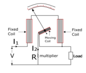
The fixed coil is divided into two sections and connected in series with the load, carrying the load current (I₁). The moving coil is connected across the load through a series resistance (R) and carries a current (I₂) proportional to the load voltage. Two spiral springs provide controlling torque, while air friction damping ensures steady pointer movement.
The Fixed Coil
The fixed coil, split into two equal halves, carries the load current. Using two coils instead of one allows the instrument to handle higher current capacity. Earlier models could carry up to 100 amperes, whereas modern wattmeters typically handle around 20 amperes to reduce power loss.
Control System
Only spring-controlled systems are used in electrodynamometer wattmeters. Gravity control systems are avoided, as they can introduce significant errors.
Damping System
Air friction damping is employed because eddy current damping would distort the weak magnetic field, leading to measurement errors. The scale used is uniform, typically allowing pointer movement between 40° and 50° on either side.
Springs
The moving coil cannot be directly connected to the power source.Hence, current is supplied through the springs, which also provide the controlling torque necessary for the pointer’s deflection.
Shielding
Since the magnetic field generated by the instrument is weak, it can be affected by external magnetic fields. To prevent this, shielding is applied using a high-permeability casing that minimizes external interference.
Working Principle
The wattmeter operates on the principle that the torque produced is proportional to the product of the instantaneous values of current and voltage in the circuit. The fixed coils carry current proportional to the load current, and the moving coil carries current proportional to the load voltage.
When current flows through both coils, magnetic fields are generated, which interact to produce a deflecting torque. This torque is proportional to the power consumed in the circuit. Thus, the deflection of the pointer on the scale indicates the true power.
Working of Electrodynamometer Wattmeter
The wattmeter has two coils — a static coil and a rotating coil. The static (fixed) coil is connected in series to measure current, while the rotating coil is connected across the supply voltage. A resistor in series with the moving coil controls the current.
The interaction between the magnetic fields of the two coils produces a torque that causes the pointer to deflect.
The degree of deflection is proportional to the power being measured.
Mathematical Expression
The instantaneous torque acting on the moving system is given by:
T₁ = i₁ iₚ (dM/dθ)
where i₁ is the current in the current coil and iₚ is the current in the pressure coil.
The voltage across the pressure coil is expressed as:
V = √2 I sin(ωt − Φ)
If the pressure coil is purely resistive, the current through it will be in phase with the voltage:
Iₚ = V / Rₚ = √2 Iₚ sin(ωt)
The average deflecting torque over one cycle is proportional to VI cos Φ,
showing that the deflection depends on the power in the circuit.
Errors in Electrodynamometer Wattmeter
- Pressure Coil Inductance: Causes the current in the pressure coil to lag behind the voltage, leading to a high reading.
- Capacitance in the Pressure Coil: Increases the power factor and results in incorrect readings.
- Mutual Inductance: Interaction between current and pressure coils may introduce phase errors.
- Eddy Current Errors: Eddy currents induce unwanted magnetic fields that disturb the main flux.
- Stray Magnetic Fields: External magnetic fields interfere with readings.
- Temperature Variation: Changes in temperature affect the resistance of the pressure coil and the torque produced by the springs.
Conclusion
The electrodynamometer wattmeter is a reliable instrument for measuring power in both AC and DC circuits. Although it is prone to certain errors, careful design, shielding, and calibration ensure high accuracy in laboratory and industrial applications.