The Hartley Oscillator is a type of LC oscillator in which the collector and base of a transistor amplifier are connected to a tuned LC circuit. The emitter is connected to a tapping point on the tuned circuit coil, which influences the oscillatory voltage. The feedback portion of the LC tank circuit is taken from the center tap of the inductor coil, or from two separate inductors connected in series and in parallel with a variable capacitor C.
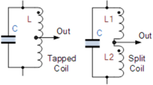
Because the coil L is center-tapped, the Hartley circuit is often called a split-inductance oscillator. When a current flows through coil section XY, it induces a signal in coil section YZ below, causing the total inductance L to act as two closely coupled coils. This configuration can be achieved using either a single tapped coil (similar to an autotransformer) or two series-connected coils in parallel with a single capacitor, as shown in typical Hartley oscillator circuits.
Basic Hartley Oscillator Design
When the circuit is oscillating, the voltage at point X (collector) relative to point Y (emitter) is 180° out of phase with the voltage at point Z (base) relative to point Y. Because the collector load impedance is resistive at the oscillation frequency, an increase in base voltage causes a decrease in collector voltage. This results in a total phase shift of 180° between the base and collector voltages.
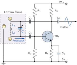
Together with an additional 180° phase shift provided by the feedback loop, this ensures the correct phase relationship for positive feedback and sustained oscillations. The amount of feedback is determined by the position of the inductor’s tapping point. Moving the tap closer to the collector increases feedback, while the output voltage (between collector and ground) decreases, and vice versa.
The capacitors in the circuit act as DC-blocking capacitors, while resistors R1 and R2 provide the transistor’s DC bias stabilization. The DC collector current flows through a portion of the coil, making this configuration a series-fed Hartley oscillator.
Frequency of Oscillation
The frequency of oscillation for a Hartley oscillator is given by:
f = 1 / (2π√(L × C))
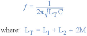
where L is the equivalent inductance of the two coils (L1 and L2) and C is the capacitance of the tuning capacitor. The oscillation frequency can be adjusted either by changing the tuning capacitor C or by adjusting the core position of the coil (inductive tuning). This makes the Hartley oscillator capable of generating a wide range of frequencies with simple tuning.
The output amplitude remains nearly constant across the entire frequency range, providing stable operation and ease of tuning.
Shunt-fed Hartley Oscillator Circuit
In the shunt-fed Hartley oscillator, both AC and DC components of the collector current follow different paths. The capacitor C2 blocks the DC component from passing through the inductive coil L, ensuring that less power is wasted in the tuned circuit.
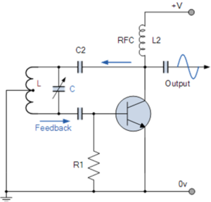
The Radio Frequency Coil (RFC), labeled as L2, acts as an RF choke with high reactance at the oscillation frequency. This allows the DC component to flow through L2 to the power supply while directing most of the RF current into the LC tuning tank circuit via capacitor C2. Although L2 can be replaced with a resistor, doing so would reduce circuit efficiency.
Hartley Oscillator Using an Operational Amplifier (Op-Amp)
A Hartley oscillator can also be built using an operational amplifier (op-amp) as the active component. The key advantage of this configuration is the ease of adjusting the amplifier’s gain using the feedback resistors R1 and R2.
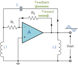
Just like in the transistor-based design, the gain of the op-amp circuit must be equal to or slightly greater than the ratio of the two inductors L1 and L2. When both inductive coils are wound on a single core and share mutual inductance M, the effective inductance ratio becomes:
(L1 + M) / (L2 + M)
This design approach simplifies the adjustment of feedback and frequency stability, making op-amp-based Hartley oscillators highly efficient and reliable for modern electronic applications.
Conclusion
The Hartley oscillator is one of the most versatile and widely used LC oscillators in electronics. Its simple design, easy tuning, and stable frequency output make it suitable for RF signal generation, frequency modulation, and waveform generation. Whether built using a transistor or an operational amplifier, the Hartley oscillator remains a fundamental circuit in analog electronics and communication systems.