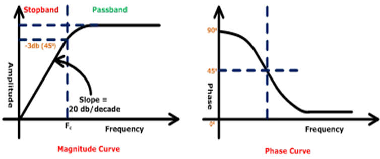
- A high pass filter is a filter that lets through high-frequency signals while obstructing or impeding low-frequency ones. In other words, it’s a high pass filter because low-frequency signals have a considerably harder time getting through whereas high-frequency signals do much better.
- Resistors can be combined with inductors, capacitors, or both to create high-pass filters. High pass RC filters are high pass filters made of a resistor and a capacitor. And a high-pass RL filter is a high-pass filter that combines an inductor and a resistor.
High Pass Filter Basics
First Order High Pass Filter
- First Class One capacitor or inductor makes up a high pass filter. This kind of filter has a first-order transfer function.
- The maximum power of “s” is one if you derive an equation in the s-domain, according to this. Only when using a single energy storage device, such as an inductor or capacitor, is this conceivable.
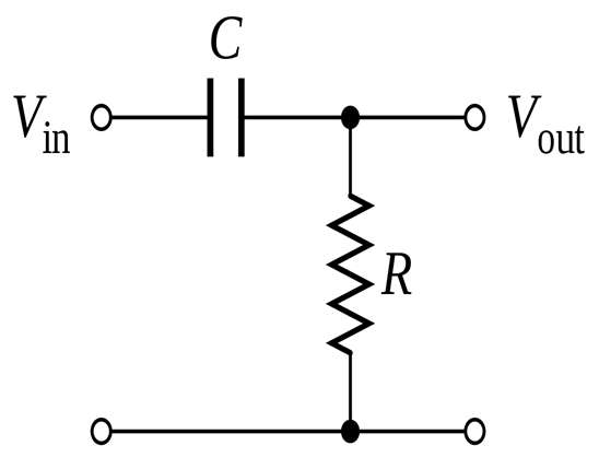
- Depending on how the elements are used, the first-order filter might be either active or passive. It can be a first-order filter if it exclusively makes use of active elements. A first-order passive high pass filter is the RC high pass filter.
Second Order High Pass Filter
- By cascading two first-order high pass filters, a second-order high pass filter can be created. As a result, it creates a second-order circuit and has two reactive components.
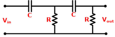
- The stop band is where the first order and second order filters differ most. The second-order filter has twice the amount of slop as the first-order filter.
One Transistor Active High Pass Filter Circuit
- A two-pole filter with unity gain is provided by the transistor high pass filter circuit shown below. The final roll-off rate will be 12 dB per decade as a result. This filter uses a single transistor and is easy to integrate into bigger circuits as it has few parts and takes up little space.
- This electronic circuit design offers only unity voltage gain for the in-band frequencies because it is fundamentally an emitter follower.
- With only four total resistors, two capacitors, and one transistor, the active high pass transistor circuit design is very simple. The transistor is set up under standard operating circumstances. The bias point for the transistor base is determined using R2 and R3. So that the highest voltage excursions can be performed without running into the rail voltage, this is frequently configured to supply the base voltage at half the rail voltage.
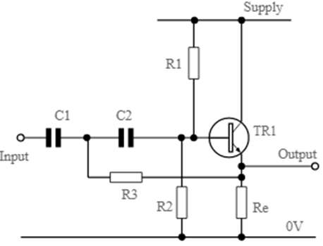
- Along with being able to supply enough current for the transistor base, the values of these resistors must be chosen so that the total value of the parallel resistors does not affect how the filter operates.
- Given that the voltage on the emitter will be 0.6 volts lower than the voltage on the base for a silicon transistor, the emitter resistor Re is calculated to provide the necessary current through the transistor. It is only 0.2 to 0.3 volts below the base voltage for a germanium transistor. Once the voltage on the emitter is known, calculating the value of the emitter resistor only requires using Ohm’s Law.
- From the circuit’s output to the input, negative feedback includes the filter components. If the input resistance to the emitter follower circuit is very high and can be disregarded, the components that make up the active filter network are C1, C2, R1, and the combination of R2 and R3 in parallel.
- The capacitors should have a comparatively tight tolerance; excellent choices include ceramic and metal film. It is not advisable to utilize aluminum electrolytic capacitors since they frequently have tolerances between -20% and +50%, which could provide undesirable performance characteristics.
- The component values are calculated using formulae that produce a Butterworth response. This filter response achieves the ultimate roll-off as soon as feasible at the expense of maximum flatness inside the passband. This was picked since the math is simple and this type of filter works well for the majority of applications. Even though not all electrical circuit designs may require this kind of filter, the majority do.
- The following equations can be used to determine the values of a single transistor high pass filter.
C1 = 2 C2R3 = R1 R2/R1+R2 - To ensure that the filter’s components are not overloaded and that the loading effect of the transistor itself does not affect the calculations.Re(β+1) >> R1 R2/R1+R2fo=2–√4 π R3 C2Where:
Β = the forward current gain of the transistor
f0 = the cut-off frequency of the high pass filter
π = the greek letter pi and is equal to 3.14159 - A little amount of iteration may be necessary while designing the circuit to optimize the value so that existing components can be used and impedance values, etc., can fall within acceptable limits.
- In situations when it might not be practical to employ another method, a straightforward circuit can be integrated using a two-pole active high pass filter. The minimal components utilized and the straightforward computations make it perfect for use.
- When a circuit to cut out low frequency hum but keep high-frequency audio is required, one transistor high pass filter circuit might be utilized.
Advantages of High Pass Filter
- They are used to filter undesirable noise during audio processing.
- At the passband’s geometric center, the magnitude response of a Butterworth filter is zero. It has a straightforward transfer function with easily calculable polynomial coefficients.
- They enable channel frequency selection in a variety of devices, including broadcast receivers.
Disadvantages of High Pass Filter
- Incorrect component value selection causes us to filter the frequency that we require.
- They remove a signal’s DC offset using filtering.
- If we don’t use the right components while employing active filters, we may end up with undesirable phase shifts at some frequencies or ripples in the passband or stopband.
Applications of High Pass Filter
- Used as an amplifier in speakers.
- In image processing, it is used to make images sharper.
- It stops DC current from being amplified, which could damage amplifiers.
- For AC coupling, they are utilized.
- They are utilized in audio processing and numerous control systems.