
Authors: Volodymyr Ilchuk, Team Lead, Application Engineering and Irena Zhuravchak, Application Engineer, Lviv, Renesas, Ukraine

This article focuses on the high-voltage section that adds H-bridge and half-bridge capability to the GreenPAK mixed-signal logic, creating a dedicated HVPAK subfamily for motor and actuator control.
We’ll walk through the key high-voltage blocks, explain how they work, and review their main configuration options. You’ll see typical application examples and how these macrocells are used in practice. Finally, you’ll have the essential knowledge needed to start driving your motor with confidence.
HVPAK Portfolio
| Key Feature\Part Number | SLG47104 | SLG47105 | SLG47115 |
| Dual Supply VDD2 | 3.0 V to 13.2 V | 3.0 V to 13.2 V | 4.5 V to 26.4 V |
| High Current Output (HCO) | 2 x 1.5 A RMS | 4 x 1.5 A RMS | 2 x 1.5 A RMS |
| Analog Comparator | 1 | 2 | 2 |
| Current Comparator | 1 | 2 | 1 |
| PWM | 1 | 2 | 2 |
| PWM Chopper | 1 | 2 | 2 |
| Differential Amplifier with Integrator and Comparator | – | 1 | 1 |
HVPAK Specialized Macrocells Overview
HV Outputs Overview
HVPAK ICs integrate N-channel power MOSFETs for High Voltage Outputs (HV OUTs) with 1.5A RMS output current capability over an input voltage range of 3.0V to 13.2V/26.4V. HV OUTs can be configured as 2x Half Bridges or x Full Bridges. See the HV OUTs block diagram in Figure 1.
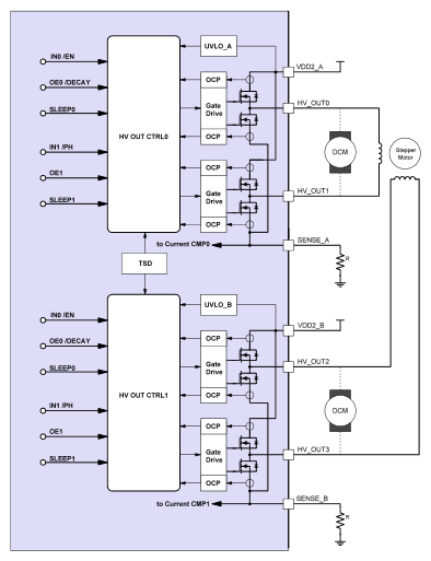
One Full Bridge can drive one bidirectional DC motor. Two Half Bridges allow driving two unidirectional DC motors. The SLG47105 features two full bridges, allowing the driving of one stepper motor.
HVPAK ICs integrate current sense pins for each HV OUT group. The motor current is sensed by monitoring the voltage across an external sense resistor. If the current limit feature is not needed, the SENSE PIN needs to be directly connected to ground.
HVPAK ICs include the following fault protections: overcurrent protection (OCP), undervoltage lockout (UVLO), and overtemperature protection (OTP). They also provide a low-power sleep mode.
Each HV OUT is the power output stage with integrated body diodes. The current flow of HV OUTs is under full control of the user by way of the input control logic. The output stage is designed to produce full load control under all system conditions. All protective and control features are integrated into the control and protection blocks. The sensors for current and temperature are integrated directly into the output MOSFET for maximum accuracy and dependability.
Pulse Width Modulator Macrocell (PWM)
HVPAK ICs feature Pulse Width Modulator (PWM) blocks. PWM is commonly used in DC motor control, LED brightness control, and other applications.
The PWM block consists of two 8-bit counters. The first one, named PWM Period CNT, is used to create a PWM period, and the second one, named Duty Cycle CNT, is used to set the PWM Duty Cycle and to make dynamic changes in the PWM functionality.
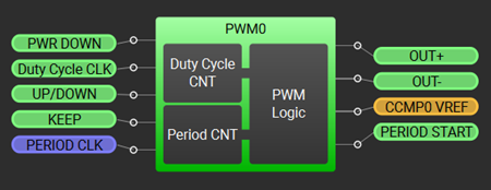
The PWM block has an 8-bit resolution by default, but a 7-bit resolution can be selected instead to allow for a higher PWM frequency. The PWM duty cycle changes at a step of 0.4 % for the 8-bit resolution and 0.8 % for the 7-bit resolution. The duty cycle can change from true 0% to true 100%. PWM starts from the Initial duty cycle value.
The block has an UP/DOWN internal connection that defines the direction of the duty cycle change.
The duty cycle in the PWM macrocell can be changed in two ways: by I2C or by matrix.
The Keep/Stop connection can either be selected to hold the duty cycle (“Keep” setting) or to hold the duty cycle and the OUT+ and OUT- outputs constant (“Stop” setting) when it is set HIGH.
The Continuous/Autostop mode is either set to “Continuous” where the PWM output duty cycle overflows when it reaches the full range value (default setting), or to” Autostop” where the PWM output stops when it reaches 0% or 100% of the duty cycle.
The PWM block features Regular mode and Preset Registers mode. In Regular Mode, the Duty cycle source is set to “Duty Cycle CNT”. In Preset Registers Mode, the duty cycle is changed according to 16 predefined values, named “Reg File”, every rising edge on Duty Cycle CLK input.
Figure 3 demonstrates the PWM block operation in more detail.
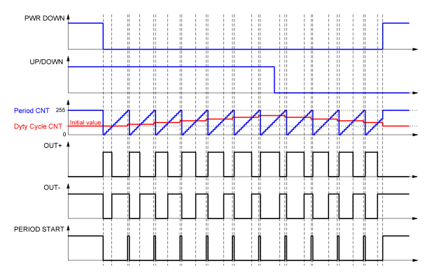
Figure 3. PWM Block Timing Diagram
Current Comparator (CCMP)
The current Comparator macrocell within HVPAK provides advanced current control. A current control circuit is provided to regulate the system in the event of an overcurrent condition, for example, an abnormal mechanical load of a DC motor. This circuit can be used for implementing constant current closed-loop systems or for current limitation.
The current is sensed by external sense resistors connected to SENSE Pins. Special current comparators are used to convert these currents to a logic level. Using a current comparator with a PWM block, the output current can be dynamically changed. For example, for a stepper motor for micro-stepping, it is possible to set 16 values for the sinusoidal current limit form.
Current Regulation
For the current regulation, it is necessary to connect a sense resistor between the SENSE pin and ground. The resulting Iref current is calculated using the formula below:
where:
- Iref – Load Current (through controlled winding or resistive load) for selected Vref
- Vref – reference voltage of Current Sense Comparator, constant value, external source, or selectable value from Register File
- RSENSE – resistance of the sense resistor
- GAIN – selectable gain (4x or 8x, selectable by the register)
PWM Chopper
HVPAK ICs contain PWM Chopper macrocells. PWM chopping detection begins after a Blanking Time during PWM operations. The Blanking Time is the time when both PWM and BLANKING signals are HIGH. During the Blanking Time, the CHOP input signal is ignored, and the PWM Chopper OUT goes HIGH and continues until the PWM signal goes LOW or the CHOP signal is detected (goes HIGH).
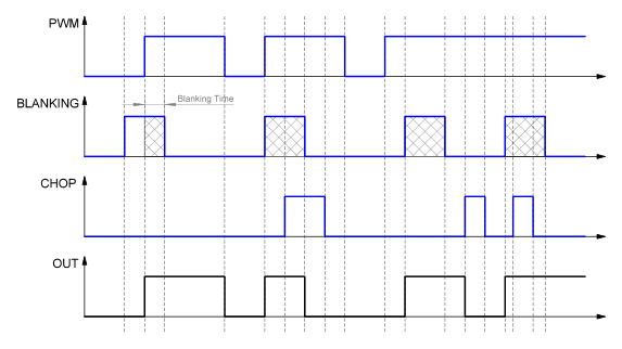
The PWM Chopper function can be used to chop the PWM duty cycle by the Current Comparator signal. This configuration allows for the Current Comparator signal to be ignored during the blanking time tied to the motor start period. Any active signal from the Current CMP after the blanking time ends the PWM pulse period.
Differential Amplifier with Integrator and Comparator
The Differential Amplifier with Integrator and Comparator (Integrator) is useful when there is a need to keep a constant voltage at the Full Bridge load (motor). This block operates synchronously with the PWM block.
The circuit monitors the voltage difference between the HV OUT PINs and integrates it to get an average DC voltage value. This voltage is divided by 4 and compared to the output voltage of the Vref of the comparator. If the averaged output voltage (divided by 4) is lower than Vref, UPWARD OUT goes HIGH; if the averaged output voltage (divided by 4) is higher than Vref, UPWARD Output goes LOW. If the averaged output voltage (divided by 4) is equal to Vref, Equal Output goes HIGH. These signals can be used to control the PWM duty cycle.
The output voltage VSET can be calculated as follows:
where Vref – reference voltage of the Comparator.
Typical Applications
Constant Voltage
The constant voltage functionality within HVPAK allows for maintaining a constant voltage on the motor regardless of the power supply or other factors. Only PWM, Differential Amplifier with Integrator and Comparator, and HV OUT CTRL blocks are needed to provide the motor control with constant voltage. The example design is shown in Figure 5.

See an example of using this feature in the application note Toy Car with Push-to-Start / Hold-to-Stop Functionality or Smart Lock Motor Driver with Voltage Regulation.
Constant Current
There are two typical solutions to create motor control with constant current.
The first one is Constant Current with Fixed PWM Frequency. The following blocks are required: CCMP, one CNT/DLY, PWM Chopper, and HV OUT CTRL. The HVPAK design is shown in Figure 6.

See an example of using this feature in the application note Stepper Motor Driver or Power Saving Solenoid Driver.
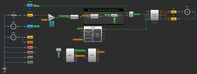
The second method is Constant Current with PWM Fixed Off-Time. To create motor control with constant current with PWM fixed off-time, the following blocks are required: CCMP, two CNT/DLYs, two 3-bit LUTs, and HV OUT CTRL. The HVPAK design is shown in Figure 7.

Figure 7. Constant Current Control with PWM Fixed Off-Time HVPAK Design
Motor Control with Soft Start/Stop
To reduce the inrush current and ensure smooth start-up and stoppage of the DC motor, the soft start/stop functionality can be utilized. It requires just one PWM block, HV OUT CTRL, two CNT/DLYs, two LUTs, and two DFFs. See Figure 8.
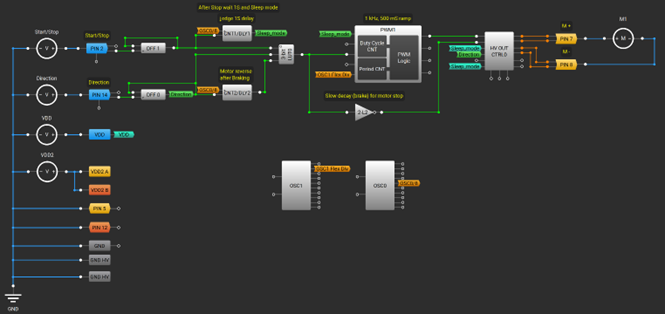
See an example of using this feature in the application note DC-DC Boost & Buzzer Driver.
Motor Stall Detection
A stall detection feature for a DC motor can be implemented using one CCMP, two CNT/DLYs, and DFF. The typical HVPAK design is shown in Figure 9.
See an example of using this feature in the application note Toy Car with Push-to-Start / Hold-to-Stop Functionality.
Half Bridges Parallel Connection
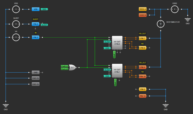
The maximum current per HVPAK output pin is 1.5 A. But if there is a need to drive a load (a DC motor in this case) with a higher current, two half bridges can be connected as shown in Figure 10.
Full Bridges Parallel Connection
The maximum current per HVPAK output pin is 1.5 A. But if there is a need to drive a load (a DC motor in this case) with a higher current, two full bridges can be connected as shown in Figure 11.
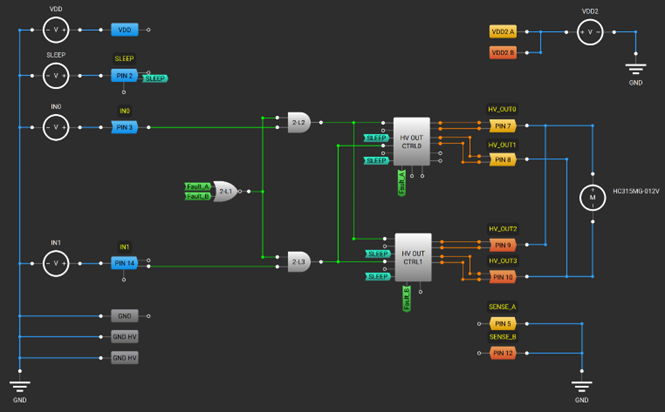
Figure 11. Full Bridges Parallel Connection HVPAK Design
Conclusion
HVPAK devices expand GreenPAK with integrated high-voltage H-bridge and half-bridge drivers, enabling compact and efficient motor-control and power solutions with minimal external components.
In this article, we explored the high-voltage macrocells that distinguish this family and reviewed how they operate. The application examples showed how easily these blocks can be combined to implement common motor-drive and switching topologies – giving you a solid starting point for your own designs.


