
Semiconductor for You
  • Home
  • Semiconductor News
  • Semiconductor Magazine
  • Technology
    • Automotive
    • Consumer Electronics
    • IoT
    • Test and Measurement
    • Lighting
    • Power Management
    • Wireless
    • Personal Electronics
    • Hardware & Software
    • Research
    • Medical Electronics
    • Embedded Design
    • Aerospace & Defence
    • Artificial Intelligence
  • Interview
  • Industries
  • Market
  • Knowledge Base
  • Events
  • Tools
    • Resistor Color Code Calculator
No Result
View All Result
  • Home
  • Semiconductor News
  • Semiconductor Magazine
  • Technology
    • Automotive
    • Consumer Electronics
    • IoT
    • Test and Measurement
    • Lighting
    • Power Management
    • Wireless
    • Personal Electronics
    • Hardware & Software
    • Research
    • Medical Electronics
    • Embedded Design
    • Aerospace & Defence
    • Artificial Intelligence
  • Interview
  • Industries
  • Market
  • Knowledge Base
  • Events
  • Tools
    • Resistor Color Code Calculator
No Result
View All Result
Semiconductor for You
No Result
View All Result
Home Knowledge Base

Kirchhoff’s Current Law

Shatabdi Pantawane by Shatabdi Pantawane
July 6, 2021
in Knowledge Base
0
ADVERTISEMENT

A German Physicist Gustav Robert Kirchhoff introduce this law in 1845. Gustav Kirchhoff’s current law is one of the fundamental laws used for circuit analysis. According to Kirchhoff’s current law, the algebraic sum of all the branch currents at a given node is zero at all instant of time. At any node in a network, the sum of the currents flowing into the node is equal to the sum of the currents flowing out of the node.


ADVERTISEMENT

   Application of Kirchhoff’s current law

  • The practical application of KCL is to determine the amount of current flowing through individual electronic components or more complex electrical circuits. Using this we can manipulate current to the component by controlling resistance to it. On a simple note we can balance a given circuit by adjusting voltage and current so that at a selected node, the current if measured is zero because the incoming current is equal to the outgoing current. So by balancing we can calculate a no. of parameters for a circuit. This is also known as Kirchhoff’s junction or Kirchhoff’s first law.
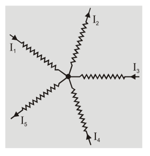
  • Here, the three currents entering the node, I1, I3, I4 are all incoming currents and are positive in value. The two current I2, I5 are outgoing currents and are negative in value.
  •  Then means we can write the equation as; I1, + I3 + I4 – I2 – I5 = 0

 

Shatabdi Pantawane

Shatabdi Pantawane

Browse by Category

  • Aerospace and Defence
  • AI & Data Center
  • Articles
  • Automation
  • Automotive
  • Communication
  • Consumer-Electronics
  • Design & Manufacturing
  • Hardware & Software
  • Healthcare
  • Industrial Electronics
  • Interview
  • IoT
  • Knowledge Base
  • Lighting
  • Market
  • personal-electronics
  • Power Management
  • Research
  • Robotics
  • Semiconductor Events
  • Semiconductor News
  • Sensors
  • Smart Home & Building
  • Technology
  • Test and Measurement
  • Uncategorized
  • Wireless
Semiconductor For You

Semiconductor For You is a resource hub for electronics engineers and industrialist. With its blend of
technology features, news and new product information, Semiconductor For You keeps designers and
managers up to date with the fastest moving industry in the world.

Follow Us

Browse by Category

  • Aerospace and Defence
  • AI & Data Center
  • Articles
  • Automation
  • Automotive
  • Communication
  • Consumer-Electronics
  • Design & Manufacturing
  • Hardware & Software
  • Healthcare
  • Industrial Electronics
  • Interview
  • IoT
  • Knowledge Base
  • Lighting
  • Market
  • personal-electronics
  • Power Management
  • Research
  • Robotics
  • Semiconductor Events
  • Semiconductor News
  • Sensors
  • Smart Home & Building
  • Technology
  • Test and Measurement
  • Uncategorized
  • Wireless

Recent News

Murata Launches Common Mode Choke Coils with Metal Terminal Structure for Automotive CAN FD Supporting Maximum Operating Temperature of 150°C

Murata Launches Common Mode Choke Coils with Metal Terminal Structure for Automotive CAN FD Supporting Maximum Operating Temperature of 150°C

September 12, 2026
Shaping the Future of Electronics: Mouser at Electronica India 2026

Shaping the Future of Electronics: Mouser at Electronica India 2026

September 11, 2026
  • About
  • Advertise
  • Privacy & Policy
  • Contact

© 2026 Semiconductor For You

No Result
View All Result
  • Home
  • Semiconductor News
  • Technology
    • IoT
    • Wireless
    • Power Management
    • Automotive
    • Hardware & Software
  • Market
  • Interview
  • Knowledge Base
  • Tools
    • Resistor Color Code Calculator

© 2026 Semiconductor For You

Advertisement