
Introduction
A multivibrator is an electronic circuit that functions as a two-stage amplifier operating in stable, unstable, and astable modes. In a multivibrator, the output of the first stage is fed to the second stage, and the output of the second stage is fed back to the first stage. This feedback action causes the cut-off state to become saturated and the saturated state to become cut-off. Due to these state transitions, multivibrators are commonly used as oscillators, timers, and flip-flops.
As the name suggests, a monostable multivibrator has only one stable state. When one transistor is conducting, the other remains in the non-conducting state. The circuit stays in this stable condition unless it is disturbed by an external trigger pulse. Because of this behavior, a monostable multivibrator is also known as a one-shot multivibrator.
Construction of a Monostable Multivibrator
The circuit consists of two transistors, Q1 and Q2, connected in a feedback configuration. The capacitor C1 connects the collector of transistor Q1 to the base of transistor Q2. The resistor R2 and capacitor C connect the base of Q1 to the collector of Q2.
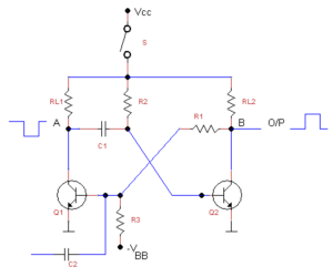
Through resistor R3, a DC supply voltage -VBB is applied to the base of transistor Q1. To change the state of Q1, a trigger pulse is applied to its base through capacitor C2. The load resistors of Q1 and Q2 are denoted by RL1 and RL2 respectively.
When one of the transistors is in a stable state, an external trigger pulse changes its condition. After the change, the circuit remains in a quasi-stable (meta-stable) state for a specific time interval determined by the RC time constant. After this interval, the circuit naturally returns to its original stable state.
Circuit Operation
Initially, the circuit is in a stable state with transistor Q1 in cut-off and transistor Q2 in saturation. Since Q2 is saturated, its collector is nearly shorted to ground, and the output at this point is low.
In this condition, the right plate of capacitor C is at approximately 0.7 V (connected to the base of Q2), while the left plate gradually charges toward VCC. When a trigger pulse is applied to the base of Q1, Q1 turns ON and current flows through its collector resistor.
This action pulls down the collector voltage of Q1, shorting the left plate of the capacitor to ground. The capacitor begins to discharge, turning transistor Q2 OFF for the duration of the discharge cycle. This Q2 OFF state is the unstable or quasi-stable state, and during this time the circuit output is high.
While Q2 is OFF, Q1 remains ON because its base is connected to the high-voltage point at the collector of Q2. Once the capacitor is fully discharged, Q2 turns ON again and Q1 returns to the OFF state, restoring the original stable condition.
The duration for which the output remains in the high state is determined by the RC time constant and is given by the formula:
T = 0.693 × R × C
To ensure proper operation, the time interval between successive trigger pulses should be greater than the RC time constant. If trigger pulses occur more frequently than this, the output will remain high, resulting in incorrect operation.
Since the output is not affected by the gradual charging of the capacitor, the monostable multivibrator produces a clean and well-defined square pulse. These circuits are compact, simple, low-cost, and widely used in timers, delay circuits, frequency dividers, and pulse generation systems.
Output Waveforms
The output waveforms at the collectors of Q1 and Q2, along with the trigger input at the base of Q1, clearly show that each trigger pulse produces a single output pulse.
The width of this output pulse is determined by the RC time constant of the circuit and is given by:
T = 0.69 × R × C
The trigger pulse is very short and only initiates the transition from the stable state to the quasi-stable (meta-stable) state. After the specified time interval, the circuit automatically returns to its original stable condition. Since the output frequency equals the trigger frequency but with an increased pulse width, monostable multivibrators are often used for pulse stretching and time delay applications.
TTL / CMOS Monostable Multivibrator
Monostable multivibrators can be constructed using discrete components like transistors, but they can also be implemented using integrated circuits. A simple monostable multivibrator can be formed using two NOR gates, as shown in standard TTL/CMOS designs.
If the trigger input is initially LOW (logic 0), the output of the first NOR gate is HIGH (logic 1). The capacitor has the same charge on both plates, and the output of the second NOR gate is LOW, which represents the stable state.
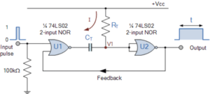
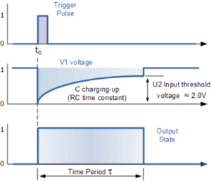
When a positive trigger pulse is applied, the output of the first NOR gate goes LOW and the capacitor begins to discharge. This causes both inputs of the second NOR gate to be LOW, resulting in a HIGH output. This is the unstable state and the output remains HIGH until the capacitor charges through the resistor to the threshold level.
Once the capacitor voltage reaches the threshold voltage, the second NOR gate returns LOW. This LOW output is fed back to the first NOR gate, which restores the circuit to its original stable state.
The time period of the IC-based circuit is given by:
T = 0.69 × R × C
Special ICs such as 74LS121, 74LS123, and 4538B are commonly used for this purpose. These ICs can produce pulse widths ranging from nanoseconds to several seconds using only two external components (R and C).
Advantages
- Only one trigger pulse is required for operation
- Simple and easy-to-design circuit
- Low cost and compact size
Disadvantages
- The timing of the trigger pulse must be greater than the RC time constant of the circuit
Applications
- Used in television and control system circuits
- Found in oscillators, counters, and flip-flops
- Used in short-term memory circuits
- Commonly used to trigger other pulse generators
- Used to reshape and regenerate weak or distorted pulses


