Introduction
A network analyzer is a primary measurement instrument used in RF and microwave engineering. Early network analyzers focused mainly on transmission and reflection measurements of active and passive components. These measurements later became the foundation for S-parameter characterization.
Over time, network analyzers evolved to include advanced features such as noise analysis, error-corrected power measurements, and frequency conversion capabilities. This article provides an overview of the network analyzer, its working principle, and its applications.
What is a Network Analyzer?
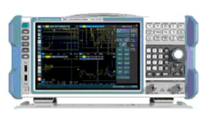
A network analyzer is an electronic instrument used to measure network parameters of an electrical circuit. At high frequencies, it primarily measures scattering parameters (S-parameters) because voltage and current measurements become difficult.
These analyzers are commonly used to analyze two-port networks such as amplifiers and filters. Other network parameters like Y, Z, and H parameters can also be derived from S-parameters.
The basic function of a network analyzer is to measure the amplitude and phase of incident and reflected waves at the ports of a Device Under Test (DUT). It includes a signal source to generate a known stimulus and receivers to measure the DUT’s response.
Why Do We Need a Network Analyzer?
A network analyzer helps engineers understand how a device or network behaves under test conditions. It allows monitoring of RF components such as filters, mixers, transistors, and frequency-sensitive circuits.
It measures transmission and reflection characteristics such as gain, insertion loss, return loss, impedance, and reflection coefficient. Network analyzers operate over a wide frequency range, from 1 Hz up to 1.5 THz, and are also used for stability analysis in audio, ultrasonic, and RF systems.
Measurements Performed by Network Analyzer
- Transmission Measurements: Gain, insertion loss, transmission coefficient
- Reflection Measurements: Return loss, reflection coefficient, impedance, VSWR
- Scattering Measurements: S11, S12, S21, and S22
Network Analyzer Block Diagram
A network analyzer consists of four main blocks: a signal source, signal separation unit, receiver or detector, and processor/display.
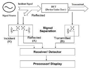
Signal Source
The signal source generates the incident signal applied to the DUT. The DUT reflects part of the signal and transmits the rest. Frequency sweeping allows complete characterization of the DUT. Common sources include sweep oscillators and synthesized signal generators.
Signal Separation
Signal separation divides the incident, reflected, and transmitted signals. This enables accurate measurement of phase and amplitude. Directional couplers, power splitters, and bridges are commonly used.
Receiver / Detector
The receiver converts RF signals into lower intermediate frequency (IF) or DC signals for accurate measurement. Detection techniques include fundamental mixing and harmonic mixing. Diode detectors are often used in Scalar Network Analyzers (SNAs), while broadband tuned receivers are used in Vector Network Analyzers (VNAs).
Processor / Display
The processor analyzes the IF signal and displays the measured parameters such as magnitude and phase on the display screen.
Working of Network Analyzer
The signal source generates an RF signal that is applied to the DUT. Signal separation divides incident, reflected, and transmitted waves. The receiver down-converts these signals to IF, which are then processed and displayed as network parameters.
Types of Network Analyzer
Scalar Network Analyzer (SNA)
Scalar Network Analyzers measure only the magnitude of signals. They are commonly used to measure return loss, VSWR, gain, and filter responses. An SNA can be created using a spectrum analyzer with a tracking generator.
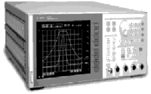
Vector Network Analyzer (VNA)
VNAs measure both amplitude and phase. They are widely used to test RF and microwave components and verify design simulations. VNAs provide detailed characterization of DUTs.
Large Signal Network Analyzer (LSNA)
LSNAs analyze devices under high-signal conditions. They evaluate nonlinear behavior, harmonics, and dynamic characteristics. Earlier versions were known as Microwave Transition Analyzers (MTA).
S-Parameters in Network Analyzer
Scattering parameters describe the relationship between input and output ports using power waves.
- S11: Input port reflection coefficient
- S12: Reverse transmission coefficient
- S21: Forward transmission coefficient
- S22: Output port reflection coefficient
S-parameters are used to calculate return loss, gain, insertion loss, and VSWR for two-port and multi-port networks.
Network Analyzer vs Spectrum Analyzer
| Network Analyzer | Spectrum Analyzer |
|---|---|
| Measures network parameters | Measures signal magnitude |
| Includes source and receiver | Includes receiver only |
| Measures known signals | Measures unknown signals |
| Supports ratioed measurements | No ratioed measurements |
| Highly accurate with calibration | Limited calibration accuracy |
| Measures phase and amplitude | Measures amplitude only |
Network Analyzer Specifications
- Frequency range: 100 kHz to 20 GHz
- Measured parameters: S11, S21, S12, S22
- Noise floor: 133 dB
- Output power range: -60 dBm to +10 dBm
- Frequency resolution: 1 Hz
Advantages of Network Analyzer
- High measurement accuracy
- Supports phase and magnitude analysis
- Advanced calibration and error correction
- Efficient RF and microwave testing
Disadvantages of Network Analyzer
- VNAs are expensive
- Complex architecture
- Slower sweep compared to SNAs
Applications of Network Analyzer
- Testing RF and microwave components
- Measuring S-parameters
- Research and development
- Material characterization
- Signal integrity analysis
- Design verification of RF systems