What is a Notch Filter?
- A notch filter (also known as a bandstop filter or reject filter) is a device that rejects or blocks the transmission of frequencies within a specific frequency range while allowing transmission of frequencies outside that range. Notch filters block transmission of a narrow frequency band while allowing transmission of all frequencies above and below this band. It is also known as a band elimination filter because it eliminates frequencies.
- A notch filter is essentially a band-stop filter with two passbands and a narrow stopband. A band-reject filter, like a band-pass filter, can be either wideband or narrowband.
- If the filter is wideband, it is called a band-reject filter, and if it is narrowband, it is called a notch filter. A band-stop filter has the exact opposite characteristics of a bandpass filter. As a result, the notch filter is a supplement to the bandpass filter.
- And thereby, the function of a Notch Filter is to pass all frequencies from zero (DC) up to the lower cut-off frequency (fL) and above the higher cut-off frequency (fH), while rejecting all frequencies that fall within the bandwidth region, i.e., BW= FH-fL.
- Signal processing techniques’ important applications include the detection and filtering of narrowband signals in the presence of noise. In many applications, the narrowband signal must be removed without changing the band energy. This is accomplished by running the signals through a notch filter.
Band Stop Filter Configuration
- In contrast to the band-pass filter, the summing of the high pass and low pass filters means that their frequency responses do not overlap. This is because their starting and ending frequencies are at different frequency points. Assume a first-order low-pass filter with a cut-off frequency of 200Hz is connected in parallel with a first-order high-pass filter with a cut-off frequency of 800Hz. Because the two filters are effectively connected in parallel, the input signal is applied to both filters at the same time, as illustrated below.
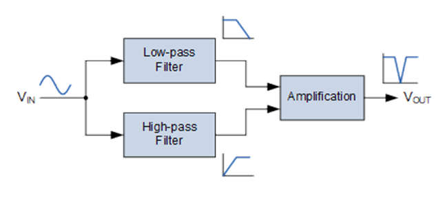
- The low-pass filter would pass all input frequencies below 200Hz unattenuated to the output. Similarly, all input frequencies above 800Hz would be unattenuated and passed to the output by the high-pass filter. However, input signal frequencies between 200Hz and 800Hz, that is, L to H, would be rejected by either filter, resulting in a notch in the filter’s output response.
Notch Filter Circuit Diagram
- A notch filter circuit diagram is shown below. As we can see, it is an active notch filter circuit with operational amplifiers. As we can see, the circuit combines a low-pass filter and a high-pass filter. The summing amplifier combines the output of the low-pass and high-pass filters. It also provides signal amplification.
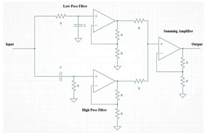
- The incorporation of operational amplifiers into the band stop filter design also allows us to incorporate voltage gain into the basic filter circuit. By simply adding input and feedback resistors, the two non-inverting voltage followers can be easily converted into a basic non-inverting amplifier with a gain of Av = 1 + R/Rin.
- Also, if we need a band-stop filter with -3dB cut-off points at 1kHz and 10kHz and a stop band gain of -10dB in between, we can easily design a low-pass and a high-pass filter with these specifications and cascade them together to form our wide-band band-pass filter design.
- Now that we understand the basic concept of a Band Stop Filter, let’s create one using the previous cut-off frequency values.
Notch Filter Response
- The notch filter, as the name implies, provides a notch or narrow band over which the filter removes signals at that frequency.
- Except for the notch frequency, the ideal response for any notch filter would be a completely flat response over the usable range. It would fall very quickly here, providing a high level of attenuation capable of removing the unwanted signal.
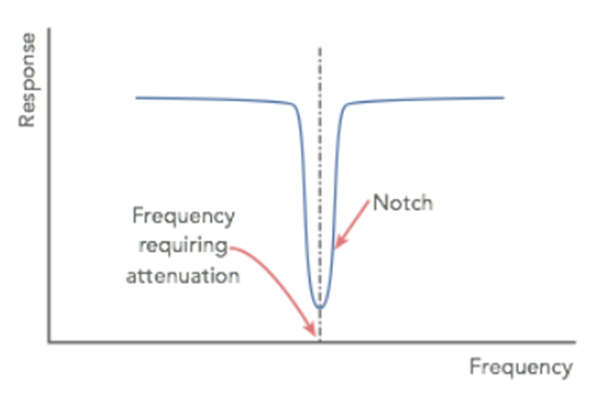
- In reality, perfection is unattainable, but when using an op amp circuit, the operational amplifier’s high levels of gain mean that high levels of attenuation and narrow notches can be easily achieved with a small number of electronic components in addition to the operational amplifier.
Notch Filter Designing
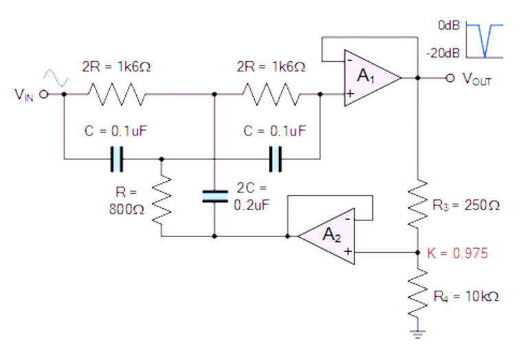
- To create a two Op-Amp narrow band RC notch filter with a 1kHz center notch frequency and a 100 Hz 3-dB bandwidth. Consider the 0.1uF capacitor and calculate all of the required component values as shown in the steps below.
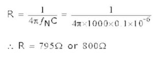
- Step 1: Determine the value of R for a capacitance of 0.1uF.
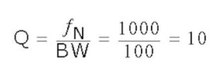
- Step 2: Determine the value of Q.
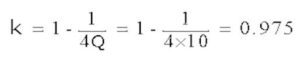
- Step 3: Determine the value of the feedback fraction K.
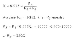
- Step 4: Determine the values of R3 and R4.
- Step 5: Finally, calculate the notch depth in dB as follows:
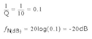
- As a result of using these values in the circuit, we can design the Notch filter as follows:
Applications of Notch Filter
- A Notch filter is commonly used to eliminate 50/60 Hz power line interference in communication systems, instrumentation and control systems, and the biomedical field.
- A notch filter, also known as a bandstop filter, is a type of filter that is widely used in electronics and communications circuits to reject a band of unwanted frequencies while allowing other frequencies to be transmitted with minimal loss.
- Sinusoidal disturbances are caused by switching type AC & DC motor drives, converters, and inverters at certain harmonics of the line frequency. The use of a notch filter removes such unwanted disturbances and allows for more accurate measurements.
- It is widely used in image and signal processing to reject unwanted frequencies, also known as noise.
- In audio signal processing, it is used to remove a specific range of unwanted frequencies, such as noise or hum.
- It is used as a line noise reducer in telephone technology, DSL, and other internet services to reduce unwanted interference. DSL stands for Digital Subscriber Line, and it is used to transmit digital data over telephone lines.
- It is used in guitar amplifiers, instrument amplifiers, acoustic guitar, mandolin, bass instrument amplifiers, and PA systems to reduce a specific humming sound produced after instruments are plugged in. It is important to note that PA (Public Address) systems are electronic systems that include microphones, amplifiers, loudspeakers, and other musical equipment.
- It is used in the medical field to eliminate the dc component in ECG (Electrocardiogram) measurements.