Half wave rectifier
- When the P-N junction diode rectifies half of the ac wave, it is called half wave rectifier.

- During positive half cycle the diode forward biased and output signal is obtained
- During negative half cycle the diode reverse biased and output signal is not obtained
- Output voltage is obtained across the load resistance RL. It is not constant but pulsating (mixture of ac and dc) in nature.
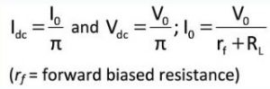
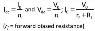
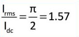
- Average output in one cycle
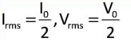
- The R.M.S. output :
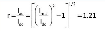
- The ratio of the effective alternating component of the output voltage or current to the dc component is known as ripple factor.
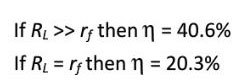
- Efficiency: It is given by

- Form factor :
- The ripple frequency (w) for half wave rectifier is same as that of ac.
Full wave rectifier

- It rectifies both half waves of ac input signal.
- During positive half cycle
- Diode : D1 forward biased
- D2 reverse biased
- Output signal obtained due to D1 only
- During negative half cycle
- Diode : D1 reverse biased
- D2 forward biased
- Output signal obtained due to D2 only
- Fluctuating dc filter constant dc
- Output voltage is obtained across the load resistance RL. It is not constant but pulsating in nature.
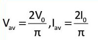
- Average output:
- Ripple factor: r=0.48=48%
- Ripple frequency: The ripple frequency of full wave rectifier = 2 x [Frequency of input cc]
- Peak inverse voltage (PIV): It’s value is 2V0
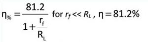
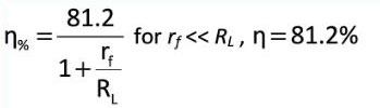
- Efficiency:
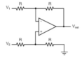
Full wave bridge rectifier
- Four diodes D1, D3, D3 and D4 are used in the circuit.
- During positive half cycle D1 and D3 are forward biased and D2 and D4 are reverse biased
- During negative half cycle D2 and D4 are forward biased and D1 and D3 are reverse biased