
Introduction
A priority encoder is a circuit or algorithm that converts multiple binary inputs into fewer outputs.
The output represents the binary index of the highest-priority active input line, starting from zero.
Priority encoders are widely used to manage interrupt requests by responding to the highest-priority input signal.
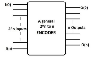
An encoder is a combinational circuit that performs the reverse operation of a decoder.
It typically has a maximum of 2n input lines and n output lines, encoding data from multiple inputs into an n-bit binary code.
When an active-high input is detected, the encoder generates the corresponding binary output.
Unlike a multiplexer, which selects a single data line to send to the output, a priority encoder generates a binary output address corresponding to the input with the highest priority.
4-to-2 Priority Encoder
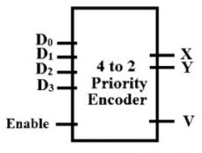
A 4-to-2 priority encoder has four inputs (D0, D1, D2, and D3)
and two outputs (X and Y).
In this type, D3 has the highest priority, while D0 has the lowest.
When multiple inputs are high simultaneously, the output represents the binary code of the highest-priority input.
For instance, if D2 is high, the output will be 10 regardless of whether D1 is high or low.
A valid output condition is indicated by a signal V, which becomes high when any input is active.
Block Diagram
Truth Table
| Inputs | Outputs | ||
|---|---|---|---|
| D3 D2 D1 D0 | X | Y | V |
| 0000 | 0 | 0 | 0 |
| 0001 | 0 | 0 | 1 |
| 001x | 0 | 1 | 1 |
| 01xx | 1 | 0 | 1 |
| 1xxx | 1 | 1 | 1 |
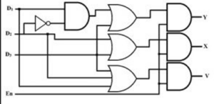
Logical Expressions
- X = D2 + D3
- Y = D1·D2’ + D3
- V = D0 + D1 + D2 + D3
The logical diagram for the 4-to-2 priority encoder uses OR, NOT, and AND gates.
According to the truth table, the output Y is 1 for input D1 only when D2 is 0.
Logical Diagram
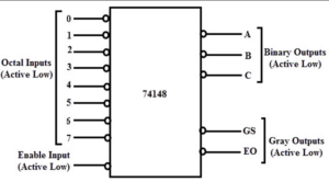
8-to-3 Priority Encoder
An 8-to-3 priority encoder (also known as an Octal to Binary Priority Encoder)
has eight inputs (D0–D7) and three outputs (A, B, and C).
When multiple inputs are active, the encoder outputs the binary code of the highest-priority input.
For example, if D1, D2, and D3 are all high,
the output corresponds to D3 (binary 011), since it has the highest priority.
Block Diagram
Truth Table
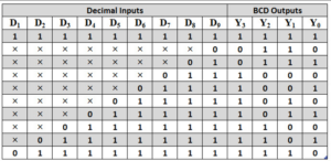
Logical Expressions
- A = D4 + D5 + D6 + D7
- B = D2 + D3 + D6 + D7
- C = D1 + D3 + D5 + D7
Logical Diagram
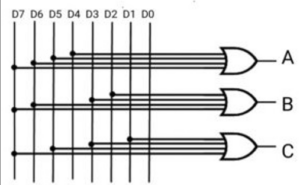
Just like the 4-to-2 encoder, the 8-to-3 encoder can be implemented using basic logic gates, where higher-numbered inputs override lower ones.
Difference Between Encoder and Priority Encoder
- A binary encoder produces an undefined output when multiple inputs are high simultaneously, leading to errors.
- A priority encoder resolves this by assigning priority to each input and producing the correct output based on the highest active input.
- Priority encoders are essential in microprocessor interrupt handling where multiple interrupt signals need to be managed according to priority levels.
- They also help reduce the number of wires and hardware complexity in multi-input circuit designs.
Applications of Priority Encoder
- Used to reduce the number of connections in complex digital systems by encoding multiple inputs efficiently.
- By cascading several encoders, larger priority encoders can be built to handle more inputs.
- Used in microprocessor systems for managing interrupt requests based on priority.
- Employed in keyboard encoding (e.g., QWERTY keyboards) where only one key is detected as pressed at a time.
- Used in flash analog-to-digital converters to encode the highest active input level.
- Commonly used in robotic control systems and magnetic positional control to convert angular or positional data into digital form.
Conclusion
A priority encoder is an essential digital circuit that simplifies multi-input systems by assigning and processing priorities.
It plays a key role in digital electronics, especially in interrupt handling, signal encoding, and control systems.


