
Introduction
An electrical waveform is a graphical representation of how a quantity such as current or voltage varies over time. It is obtained by plotting the instantaneous values of voltage or current with respect to time or angle. The resulting shape or pattern is called a waveform.
In many cases, the medium through which a wave travels makes it impossible to observe the wave’s true form directly. An oscilloscope is commonly used to display a waveform as a repeating pattern on a screen.
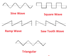
A waveform shows how alternating current (AC) changes over time. The most familiar AC waveform is the sine wave, where current or voltage varies with the sine of elapsed time. Other common waveforms include the square wave, ramp wave, sawtooth wave, and triangular wave.
Some AC waveforms are irregular or complex. For example, low-end UPS systems, audio amplifiers, and certain oscillators can generate square or sawtooth waves instead of pure sine waves.
A perfect sine wave represents energy concentrated at a single frequency. For instance, household AC supply in most countries has a sine waveform of 50 Hz or 60 Hz.
What is an Electronic Waveform?
An electronic waveform visually represents voltage or current as it changes over time. The horizontal (x) axis represents time, while the vertical (y) axis represents the quantity being measured — typically voltage or current.
When analyzing waveforms, we categorize them as:
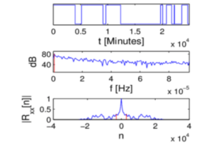
- Non-Periodic Waveforms: These waveforms vary randomly and do not repeat over time. Examples include noise or control signals responding to unpredictable inputs.
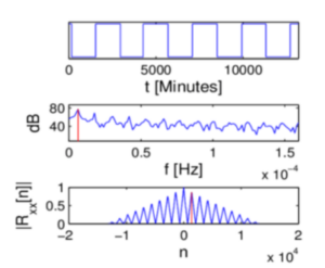
- Periodic Waveforms: These repeat at regular intervals, making them useful in signal generation and analysis. Examples include sine, square, ramp, and triangular waveforms.
Key Characteristics of a Periodic Waveform
1. Period (T)
The period is the time taken for one complete cycle of the waveform, measured in seconds (s). It can also be expressed using submultiples like milliseconds (ms) or microseconds (μs). The symbol T denotes the period.
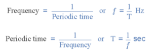
2. Frequency (f)
The frequency of a waveform is the number of cycles it completes in one second. It is measured in Hertz (Hz). Frequency and period are reciprocals of each other:
f = 1 / T
Common frequency units include kilohertz (kHz), megahertz (MHz), and gigahertz (GHz).
3. Amplitude
The amplitude represents the maximum magnitude of the waveform, measured in volts (V) or amps (A). It indicates the strength or intensity of the signal.
Sine Wave
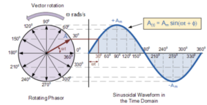
A sine wave is a smooth, continuous waveform defined by the equation y = sin(x). It oscillates symmetrically above and below a zero reference line.
The time for one full cycle is called the period (T), and the number of cycles per second is the frequency (f). They are mathematically related as:
f = 1 / T
A complete sine wave cycle is equivalent to 360° or 2π radians. As the period decreases, frequency increases, and vice versa.
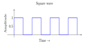
Square Wave
A square wave is a type of non-sinusoidal periodic waveform that alternates instantly between two levels — high and low. Ideally, transitions between states are instantaneous, but in reality, finite rise and fall times occur.
When the high and low durations are equal, the square wave has a 1:1 mark-to-space ratio. If they differ, the waveform becomes rectangular.
Key Parameters of a Square Wave:
- Time Period: The duration of one complete cycle, measured from one rising (or falling) edge to the next.
- Frequency: Number of times the waveform repeats in one second, measured in Hertz (Hz).
- Amplitude: The voltage difference between the high and low levels. In digital circuits, standard TTL logic defines 0–0.4V as low and 2–5V as high.
Square waves are widely used in digital circuits, pulse generation, and clock signals for microcontrollers and processors.
Triangular Wave
A triangular wave consists of two linear ramps — one rising and one falling — forming a symmetrical shape. The voltage increases linearly to a maximum point and then decreases at the same rate to a minimum point.
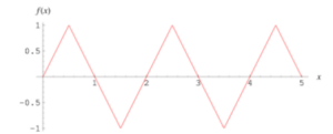
If both slopes are equal, the waveform has a 50% duty cycle. However, a non-symmetrical triangular waveform may have different rise and fall rates, leading to a sawtooth wave.
Mathematical Properties:
The triangular wave comprises only the odd harmonics of the fundamental frequency, and the amplitude of each harmonic is proportional to 1 / (harmonic number)2.
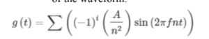
Triangular waves can be generated using function generators or by integrating a square wave. They can also be converted into a sine-like waveform using diode-based shaping circuits.
Conclusion
Understanding different electrical waveforms—such as sine, square, and triangular waves—is essential in electronics, communication, and signal processing. Each waveform type has distinct characteristics and applications, from power transmission and oscillators to digital logic and waveform generation.