
Introduction
A Silicon Controlled Rectifier (SCR), also known as a semiconductor-controlled rectifier, is a solid-state current-controlling device made of four-layer PNPN semiconductor material. The SCR was invented in 1956 by Moll, Tanenbaum, Goldey, and Holonyak of Bell Laboratories. 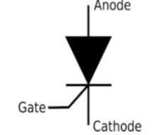
SCRs belong to the thyristor family, which includes devices such as TRIAC, GTO, SCS, DIAC, UJT, and PUT. This article focuses mainly on SCR operation and its use in practical circuits.
SCRs are unidirectional devices—they conduct current in only one direction. In contrast, TRIACs are bidirectional and can be triggered using either polarity on the gate. SCRs can only be triggered using a positive gate current.
Silicon Controlled Rectifier (SCR)

An SCR is a four-layer PNPN device with a gate terminal, as shown in the standard symbol. When triggered, it behaves like a diode in the forward direction. Without gate activation, the SCR remains non-conductive.
The operation of the SCR can be explained using its transistor equivalent model, which consists of one NPN and one PNP transistor. A positive gate signal through the gate–cathode junction turns the NPN transistor ON, which in turn triggers the PNP. This regenerative action keeps the SCR conducting even after the gate signal is removed, as long as a positive anode voltage is present.

Conduction stops when the anode current drops to zero, which naturally occurs in AC circuits at every zero crossing. In high-power SCRs, the doping profile spans across a thick wafer, with heavily doped P+ (anode) and N+ (cathode) layers and lightly doped middle layers.
SCR and GTO Symbols
The SCR symbol indicates unidirectional conduction with a gate terminal. A GTO (Gate Turn-Off Thyristor) has bidirectional arrows near the gate, signifying that conduction can be turned ON or OFF using gate signals.
Along with silicon-based SCRs, silicon-carbide (SiC) SCRs have been developed for high-temperature and high-power applications due to SiC’s excellent thermal conductivity.
DC Thyristor / SCR Circuit
SCR circuits are used widely to control DC loads such as motors, lamps, and heating elements.
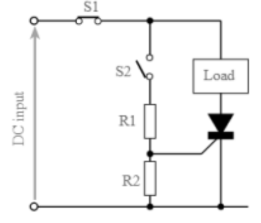
The basic DC SCR circuit operates as follows:
- With switch S1 closed and S2 open, no current flows.
- When S2 is closed, gate current flows through resistor R1, triggering the SCR, and the load receives power.
- Once triggered, the SCR continues to conduct until the anode circuit is interrupted.
- S1 is used to interrupt the anode current and turn OFF the SCR.
R1 is used to set the correct gate current. R2 is added to prevent false triggering from noise.
Basic AC Thyristor / SCR Circuit
In AC circuits, SCR operation differs because AC voltage reverses polarity each cycle:
- During the positive half cycle, the SCR can be triggered if sufficient gate voltage is applied.
- It remains conducting until the AC waveform reaches zero.
- During the negative half cycle, the SCR is reverse-biased and remains OFF naturally.
Thus, an OFF switch is not required in AC circuits because each negative half cycle naturally commutates the SCR.
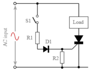
However, this circuit delivers power only during the positive half cycle, meaning maximum power delivered is approximately 50% of the AC waveform.
Applications of SCR
- Power switching circuits
- Controlled rectifiers
- AC power control circuits
- Speed control of DC motors
- SCR crowbar protection
- Computer logic circuits
- Timing circuits
- Inverters
- Battery charging regulators
- Temperature control systems