• Home
  • About Us
  • Contact Us
Semiconductor for You
  • Home
  • Semiconductor News
  • Technology
    • Automotive
    • Consumer Electronics
    • IoT
    • Lighting
    • Power Management
    • Wireless
    • Personal Electronics
    • Hardware & Software
    • Research
    • Medical Electronics
    • Embedded Design
    • Aerospace & Defence
    • Artificial Intelligence
  • DIY Projects
  • Market
  • Industries
    • Renesas Electronics
  • Knowledge Base
  • Events
  • Tools
    • Resistor Color Code Calculator
No Result
View All Result
Semiconductor for You
No Result
View All Result
Home Knowledge Base

TCS 3200 – Pin Diagram, Circuit and Applications

Mrinali Sharma by Mrinali Sharma
August 26, 2022
in Knowledge Base
0
ADVERTISEMENT
  • Color Sensor Module has 4 LEDs with TCS3200 Color Sensor IC.
  • The module is designed in such a way that 4 bright LEDs will light the object and reflections from that object will strike the TCS3200 Color Sensor IC to detect the color of an object.
  • TCS3200 is a programmable color-to-frequency converter, that gives square wave output with frequency directly proportional to the light sensitivity.
  • It consists of an 8×8 array of photodiodes i.e. 64 photodiodes.
  • Of the total 64 photodiodes, 16 photodiodes have Red filters, 16 photodiodes have Green filters, 16 photodiodes have Blue filters, and 16 photodiodes are Clear with No filters.
  • All photodiodes of the same color are connected in parallel.
  • This sensor gives us object color in form of RGB (Red, Green, Blue) values, from which we can define the object color.

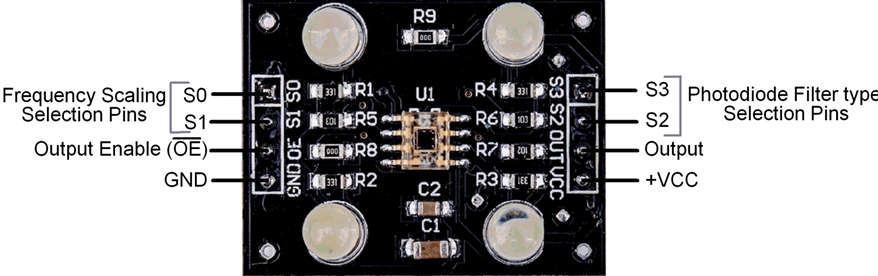
Block Diagram and Pin Diagram

Block Diagram of TCS 3200

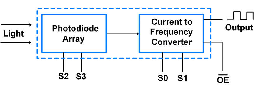
Pin 1:2 – S0:S1: Output frequency scaling selection pins.

  • These two pins are used to scale the frequency of the current to the frequency converter.

Pin 3 – OE (Active Low): Output Enable

  • 0= Output pin is enabled.
  • 1= Output pin is in High-Impedance state.

Pin 4:5 – GND: VCC

  • GND= Power Supply Ground.
  • VCC= Supply Voltage to the sensor.

Pin 6 – Output

  • This pin gives output in the form of a train of pulses. The duty cycle of these pulses is fixed to 50% and the frequency of these pulses is varying according to the input light.

Pin 7:8 – S2:S3 – Photodiode filter type selection pins

Pin Configuration of TCS 3200

Applications of TCS 3200

  • TCS3200 is applied for industrial process control.
  • In laser edge banding machines to detect color TCS3200 is used.
  • To detect chronic kidney diseases TCS3200 is used for urine analysis.
  • TCS3200 is used in fruit sorting systems.
  • The intensity of blue, red, and green radiations can be measured using this sensor module.
Content Protection by DMCA.com
Mrinali Sharma

Mrinali Sharma

Browse by Category

  • Aerospace and Defence
  • Articles
  • Automotive
  • Consumer-Electronics
  • Hardware & Software
  • Interview
  • IoT
  • Knowledge Base
  • Lighting
  • Market
  • personal-electronics
  • Power Management
  • Research
  • Semiconductor Events
  • Semiconductor News
  • Technology
  • Wireless
Semiconductor for You

Semiconductor For You is a resource hub for electronics engineers and industrialist. With its blend of
technology features, news and new product information, Semiconductor For You keeps designers and
managers up to date with the fastest moving industry in the world.

Follow Us

Browse by Category

  • Aerospace and Defence
  • Articles
  • Automotive
  • Consumer-Electronics
  • Hardware & Software
  • Interview
  • IoT
  • Knowledge Base
  • Lighting
  • Market
  • personal-electronics
  • Power Management
  • Research
  • Semiconductor Events
  • Semiconductor News
  • Technology
  • Wireless

Recent News

New SPI Absolute Encoder Supports 9 mm to 15.875 mm Motor Shafts

New SPI Absolute Encoder Supports 9 mm to 15.875 mm Motor Shafts

June 11, 2025
Infineon Secures the Future with 10 Billion Integrity Guard Chips Delivered

Infineon Secures the Future with 10 Billion Integrity Guard Chips Delivered

June 11, 2025
  • About
  • Advertise
  • Privacy & Policy
  • Contact

© 2022 Semiconductor For You

No Result
View All Result
  • Home
  • Semiconductor News
  • Technology
    • IoT
    • Wireless
    • Power Management
    • Automotive
    • Hardware & Software
  • Market
  • Knowledge Base
  • Tools
    • Resistor Color Code Calculator

© 2022 Semiconductor For You