
Introduction
A Vacuum Tube Voltmeter (VTVM) is an electronic voltmeter that uses vacuum tubes for measuring voltages, especially in circuits where only very small currents can be drawn without affecting the actual voltage levels. VTVMs offer several advantages such as high input impedance, wide frequency range, and high sensitivity. They draw significantly less current compared to conventional meters because the measuring signal is directly applied to the vacuum tube, where it is amplified and then displayed on the meter.
Types of Vacuum Tube Voltmeters
The common types of VTVMs include:
- Diode-Type Peak Reading Vacuum Tube Voltmeter
- Single Triode Type
- Balanced Triode Type
- Rectifier–Amplifier Type
- Amplifier–Rectifier Type
Simple Diode-Type VTVM
A simple diode voltmeter consists of a PMMC meter, a load resistor, and a vacuum tube diode. The diode amplifies weak signals, making the system more sensitive than standard voltmeters. To achieve accurate readings, the current and voltage must remain proportional, which is ensured by the series resistance connected to the diode.

Since the series resistor has very high resistance compared to the vacuum tube diode, the diode’s resistance is negligible. This results in a linear voltage-current relationship, and the PMMC meter deflects proportionally to the input voltage.
Key Points
- The input resistance of the voltmeter equals the series resistance.
- A higher series resistance reduces the frequency range of the voltmeter.
- Due to limited frequency range and low input resistance, this type is used in fewer applications.
Peak Reading Diode VTVM
In this type, a capacitor is added to the circuit. If the capacitor is in series with the resistor, it is called a Series Type Peak Reading VTVM. If it is connected in parallel with the resistor, it becomes a Compensated Shunt Type VTVM.
The operation of both types is similar. The capacitor charges during the positive peak of the AC input and discharges through the resistor, creating a voltage proportional to the peak value. A PMMC meter connected in series rectifies and displays this peak voltage.
Although VTVMs were widely used earlier, they have mostly been replaced by Transistor Voltmeters (TVM), Field-Effect Voltmeters (FEV), and FET Voltmeters (FETVM).
Additional Advantages of VTVM
VTVMs excel in applications requiring accurate AC voltage measurement over a wide frequency bandwidth. They are ideal for monitoring changing signal voltages in high-impedance circuits, such as audio amplifier stages. Most digital multimeters are accurate only up to about 400 Hz, making VTVMs useful for higher-frequency AC measurements.
VTVM DC Voltage Measurement
When the VTVM probe is connected to a DC voltage source, the current through the first vacuum tube (V1) increases, causing a voltage drop across resistor R2. This makes the right side of the meter movement more positive, allowing current to flow through the meter. The deflection is directly proportional to the voltage applied to the grid of V1.
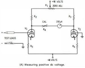

A calibration control (CAL) is connected in series with the meter but is used only during calibration, not during measurements. Typically, switching circuits inside a VTVM apply the voltage to different triodes depending on polarity. This isolates the meter movement from the circuit under test, protecting it from overload.
VTVM AC Voltage Measurement

To measure AC voltages, the DC-measuring bridge circuit is preceded by a rectifier. During the positive half cycle of the AC signal, the diode conducts and charges capacitor C2 to the peak voltage. Because resistor R is large, the capacitor does not discharge fully before the next cycle, resulting in a voltage proportional to the AC peak value.
Twin-Rectifier (Voltage Doubler) Method
A twin rectifier is often used for improved AC measurement. In this method:
- Diode V1 charges capacitor C1 to the positive peak voltage.
- During the negative half cycle, V1 stops conducting and diode V2 conducts, charging C2.
- The combined voltage results in a peak-to-peak output applied to the bridge amplifier.
The meter scale is usually calibrated in RMS, peak, or peak-to-peak values for sine-wave signals. A zero-adjust potentiometer (R2) ensures correct zero deflection when no voltage is applied.


