• Home
  • About Us
  • Contact Us
Semiconductor for You
  • Home
  • Semiconductor News
  • Magazine
  • Technology
    • Automotive
    • Consumer Electronics
    • IoT
    • Lighting
    • Power Management
    • Wireless
    • Personal Electronics
    • Hardware & Software
    • Research
    • Medical Electronics
    • Embedded Design
    • Aerospace & Defence
    • Artificial Intelligence
  • DIY Projects
  • Market
  • Industries
    • Renesas Electronics
  • Knowledge Base
  • Events
  • Tools
    • Resistor Color Code Calculator
No Result
View All Result
Semiconductor for You
No Result
View All Result
Home Knowledge Base

Weston Frequency Meter: Working Principle, Construction, Advantages & Applications

Komal Ganvir by Komal Ganvir
November 27, 2025
in Knowledge Base
0

Introduction

The Weston type frequency meter operates on the deflection principle to measure the unknown frequency of an input signal. It consists of two main coils: an inductive coil and a resistive coil. When the input frequency deviates from the standard frequency, the current distribution between these coils changes, which results in a corresponding pointer deflection.

Operating Principle

The Weston frequency meter works by passing current through two coils placed 90° apart. The magnetic field created by these currents causes the needle to deflect toward the coil producing the stronger field. This deflection indicates the unknown frequency of the input signal.

Construction

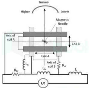
The magnetic axes of the two coils, A and B, are positioned perpendicular to each other. A long, thin soft-iron needle is placed at their center. The needle assembly includes a pointer and damping vanes but has no controlling device.

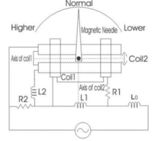
The overall circuit resembles a Wheatstone bridge balanced at the supply frequency. Coil A is connected in series with resistance RA and in parallel with reactance LA. Similarly, coil B is connected in series with resistance RB and in parallel with reactance LB. A series inductance L0 is used to suppress higher harmonics, reducing waveform errors. At standard frequency, the meter is manufactured such that the pointer rests at 45°.

Working

When power is applied, currents begin to flow in coils A and B, creating perpendicular magnetic fields. The needle deflects based on the relative strength of these fields. At normal frequency, equal voltage drops occur across LA and RB, resulting in equal current in both coils. Thus, the needle rests at the center of the scale.

When the input frequency increases, reactance’s LA and LB increase while resistances remain constant. The rising impedance of coil A reduces its current, while coil B receives comparatively more current. This makes the pointer move toward coil B, indicating a higher frequency. When the frequency decreases, the opposite occurs, and the pointer deflects toward coil A.

Advantages

  • Highly sensitive instrument
  • Simple construction
  • Linear frequency scale
  • Readings are unaffected by voltage variations
  • Applicable for a wide range of voltages

Disadvantages

  • Susceptible to temperature variations
  • Rectifiers in the circuit may cause distortion, affecting accuracy

Applications

  • Testing radio and communication equipment
  • Used in laboratories for measuring frequency-related transducer outputs
Content Protection by DMCA.com
Tags: Weston Frequency Meter
Komal Ganvir

Komal Ganvir

Browse by Category

  • Aerospace and Defence
  • Articles
  • Automotive
  • Consumer-Electronics
  • Hardware & Software
  • Interview
  • IoT
  • Knowledge Base
  • Lighting
  • Market
  • personal-electronics
  • Power Management
  • Research
  • Semiconductor Events
  • Semiconductor News
  • Technology
  • Wireless
Semiconductor for You

Semiconductor For You is a resource hub for electronics engineers and industrialist. With its blend of
technology features, news and new product information, Semiconductor For You keeps designers and
managers up to date with the fastest moving industry in the world.

Follow Us

Browse by Category

  • Aerospace and Defence
  • Articles
  • Automotive
  • Consumer-Electronics
  • Hardware & Software
  • Interview
  • IoT
  • Knowledge Base
  • Lighting
  • Market
  • personal-electronics
  • Power Management
  • Research
  • Semiconductor Events
  • Semiconductor News
  • Technology
  • Wireless

Recent News

Owen’s Bridge: Construction, Theory, Balance Equations, Advantages & Disadvantages

Owen’s Bridge: Construction, Theory, Balance Equations, Advantages & Disadvantages

November 27, 2025
Resistance Thermometer (RTD): Construction, Working Principle, Equation, Advantages & Applications

Resistance Thermometer (RTD): Construction, Working Principle, Equation, Advantages & Applications

November 27, 2025
  • About
  • Advertise
  • Privacy & Policy
  • Contact

© 2022 Semiconductor For You

No Result
View All Result
  • Home
  • Semiconductor News
  • Technology
    • IoT
    • Wireless
    • Power Management
    • Automotive
    • Hardware & Software
  • Market
  • Knowledge Base
  • Tools
    • Resistor Color Code Calculator

© 2022 Semiconductor For You