

Introduction
A MOD counter, also known as a modulus counter, is a sequential logic circuit that counts a predetermined number of states in response to clock pulses. After reaching its final counting state, the counter returns to its initial state and repeats the counting sequence. MOD counters are widely used in digital electronics, frequency division, digital clocks, timers, counters, and other sequential logic applications.
What is a Counter?
A counter is a sequential logic circuit that advances its counting state by one for every clock pulse. Depending on its operation, a counter can work in count-up, count-down, or bidirectional mode.


- Count-Up Counter: Advances through the counting sequence in increasing order.
- Count-Down Counter: Advances through the counting sequence in decreasing order.
- Bidirectional Counter: Can count in both UP and DOWN directions.
Counters can also be classified as synchronous and asynchronous counters. In a synchronous counter, all flip-flops receive the clock signal simultaneously. In an asynchronous counter, the output of one flip-flop is used to trigger the next flip-flop.

What is a MOD Counter?
The modulus, or MOD, of a counter represents the number of unique states through which the counter passes before returning to its initial state. For example, a 2-bit binary counter has four possible states:
- 00
- 01
- 10
- 11
After the state 11, the counter returns to 00. Therefore, it is called a MOD-4 counter. For a binary counter using n flip-flops, the maximum number of states is:
MOD = 2n
Thus, counters with 1, 2, 3, and 4 flip-flops can naturally provide MOD-2, MOD-4, MOD-8, and MOD-16 counting sequences respectively.
D-Type Flip-Flop in MOD Counters
MOD counters are constructed using flip-flops. Different types of flip-flops, including S-R, J-K, D-type, and T-type flip-flops, can be used to design counters.
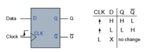

A D-type flip-flop has a single data input, called D, and a clock input, called CLK. The output changes according to the input at the triggering edge of the clock signal. The TTL 74LS74 is an example of a D-type flip-flop. Depending on the configuration, edge-triggered flip-flops can respond to either the rising or falling edge of a clock pulse.
Working of a D-Type Flip-Flop
A D-type flip-flop transfers the value present at its D input to the Q output when the triggering clock edge occurs.
| D Input | Q Output | Operation |
|---|---|---|
| 0 | 0 | Reset |
| 1 | 1 | Set |
The flip-flop retains its previous output between triggering clock edges.
Divide-by-2 Counter
A D-type flip-flop can be configured as a divide-by-2 counter by connecting the complementary output back to the D input. With this feedback configuration, the flip-flop changes its state on every triggering clock edge.
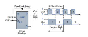

As a result, the frequency of the Q output becomes half of the input clock frequency.
fout = fin / 2
Frequency Division Using Multiple Flip-Flops
When additional flip-flops are connected in stages, each stage divides the frequency by 2. Therefore, an n-stage binary counter can provide a frequency division of:
fout = fin / 2n
For example, a sequence of frequency divisions can be used to reduce a 60 Hz signal to a lower-frequency timing signal.
MOD-2 Counter
A single flip-flop can be considered a MOD-2 counter because it has two possible output states: 0 and 1.
The counter follows the sequence:
0 → 1 → 0 → 1 → …
Therefore, one flip-flop provides a modulus of 2 and divides the input frequency by 2.
MOD-4 Counter
When two flip-flops are connected to form a binary counter, the counter has four possible states and is therefore called a MOD-4 counter.
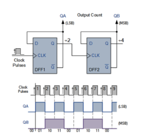

The counting sequence is:
00 → 01 → 10 → 11 → 00 → …
The input frequency is divided by 4 at the complete counter output cycle.
MOD-4 Counter Truth Table
| Clock Pulse | QB | QA | Next State |
|---|---|---|---|
| 0 | 0 | 0 | 01 |
| 1 | 0 | 1 | 10 |
| 2 | 1 | 0 | 11 |
| 3 | 1 | 1 | 00 |
After four clock pulses, the counter returns to its initial state of 00 and repeats the sequence.
MOD-8 Counter
Adding a third flip-flop to a binary counter creates a MOD-8 counter. Since three flip-flops can represent:
23 = 8
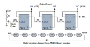

the counter has eight possible states, ranging from 000 to 111. The counting sequence is:
000 → 001 → 010 → 011 → 100 → 101 → 110 → 111 → 000
Similarly, adding a fourth flip-flop produces a MOD-16 counter.
Natural MOD Counters
A binary counter using n flip-flops naturally provides 2n states. Therefore, commonly used natural MOD counters include:
| Number of Flip-Flops | Maximum States | Counter |
|---|---|---|
| 1 | 2 | MOD-2 |
| 2 | 4 | MOD-4 |
| 3 | 8 | MOD-8 |
| 4 | 16 | MOD-16 |
However, digital systems often require counters with a modulus that is not a power of two, such as MOD-3, MOD-5, MOD-6, or MOD-10.
Counters of Modulo M
A modulo-M counter does not necessarily use all the available binary states. Instead, additional logic is used to detect a particular state and reset the counter to zero. For a counter with n flip-flops, the maximum number of available states is:
2n
To design a MOD-M counter, the required number of flip-flops must satisfy:
2n ≥ M
Additional combinational logic can then be used to detect the required state and reset the counter.
Clear and Preset Inputs
Flip-flops used in counters may include CLEAR and PRESET inputs. The CLEAR input can reset the counter outputs to zero, while the PRESET input can set the flip-flop outputs to a specified state. Some counters also include ENABLE or INHIBIT inputs that allow counting to be stopped temporarily while retaining the current state.
MOD-5 Counter
A MOD-5 counter has five counting states: 0 through 4.
Since:
22 = 4 < 5
and:
23 = 8 ≥ 5
a MOD-5 counter requires at least three flip-flops. The required counting sequence is:
000 → 001 → 010 → 011 → 100 → 000 → …
How a MOD-5 Counter Works
A basic 3-bit counter can naturally count from 000 to 111. To convert it into a MOD-5 counter, additional combinational logic detects the binary state corresponding to decimal 5:
1012 = 510
When this state is detected, the logic generates a reset signal that returns the counter to 000. A 3-input AND gate and inverter can be used as part of the decoding logic. The decoded output is connected to the clear/reset circuitry of the counter. The counter therefore spends only a very short time in the detected reset state before returning to 000. This allows the counter to operate with five effective counting states.
Advantages and Limitation of Asynchronous MOD Counters
Asynchronous counters can be used to create different MOD counters by decoding a particular output state and resetting the counter. However, propagation delays and temporary unwanted output states can occur during the reset process. These unwanted transient effects are sometimes referred to as glitches. For applications where simultaneous state changes are important, synchronous counters may be preferred.
MOD-10 Counter or Decade Counter
A MOD-10 counter, also known as a decade counter, has ten counting states, from 0 to 9.
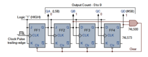

The counting sequence is:
0000 → 0001 → 0010 → 0011 → 0100 → 0101 → 0110 → 0111 → 1000 → 1001 → 0000
When the counter reaches 9, represented by 1001 in binary, it resets to 0000 instead of continuing to 1010. Decade counters are useful for applications involving digital displays and decimal counting. The TTL 74LS90 is an example of a decade counter.
MOD Counter Examples
| Counter | Number of States | Counting Range |
|---|---|---|
| MOD-2 | 2 | 0–1 |
| MOD-4 | 4 | 0–3 |
| MOD-5 | 5 | 0–4 |
| MOD-8 | 8 | 0–7 |
| MOD-10 | 10 | 0–9 |
Applications of MOD Counters
- Digital clocks and timers
- Frequency division
- Digital displays
- Event counting
- Sequential logic circuits
- Timing and control circuits
- Digital frequency counters
- Communication and control systems
MOD Counter Summary
A MOD counter is a sequential logic circuit that passes through a fixed number of unique states before returning to its initial state. The modulus represents the total number of states in one complete counting cycle. For a natural binary counter using n flip-flops:
MOD = 2n
For example, a three-flip-flop counter provides eight states and is therefore a MOD-8 counter. Similarly, a MOD-10 counter has ten states and is commonly known as a decade counter. MOD-2, MOD-4, MOD-8, and MOD-16 counters are natural binary counters, while counters such as MOD-5, MOD-6, and MOD-10 require additional logic to reset the counter at the desired state.
Conclusion
MOD counters are important sequential logic circuits used for counting, frequency division, timing, and digital control applications. By changing the number of flip-flops and adding appropriate decoding logic, counters can be designed for different modulus values. Understanding MOD-2, MOD-4, MOD-5, MOD-8, and MOD-10 counters provides a strong foundation for studying digital counters, frequency dividers, digital clocks, and other sequential logic systems.