
Introduction
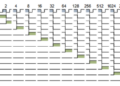
A binary ripple counter is a versatile digital IC that can be used to build a simple LED flasher circuit. It is a popular project among electronics students and hobbyists because it requires relatively few components and demonstrates frequency division and sequential counting. Ripple counters use cascaded flip-flops as frequency dividers. Each stage divides the clock frequency by 2, allowing a higher-frequency clock signal to be converted into lower-frequency signals that can be used to control LEDs.
What is a Ripple Counter?
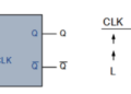
A ripple counter is an asynchronous counter in which the flip-flops do not all change state simultaneously. Instead, the output of one flip-flop is used to trigger the next stage. The resulting change propagates through the counter like a ripple. In many ripple-counter configurations, the flip-flops toggle on the falling or negative edge of the clock signal. The basic building block of a ripple counter is a toggle, or T-type, flip-flop. Multiple divide-by-2 stages can be cascaded to create a larger frequency divider.

Binary Ripple Counter as a Frequency Divider
Ripple counters can be constructed from a series of divide-by-2 stages. Each stage divides the frequency of the signal from the previous stage by 2. Therefore, the output frequency at the nth stage can be represented as:
fout = fin / 2n
For example:
| Output Stage | Frequency Division | Output Frequency |
|---|---|---|
| Q1 | 2 | fin / 2 |
| Q6 | 64 | fin / 64 |
| Q12 | 4096 | fin / 4096 |
Several binary ripple counter ICs are available, including the 74LS93 4-bit counter, CMOS 4024 7-bit counter, CMOS 4040 12-bit counter, and CMOS 4060 14-bit counter.
CD4040B 12-Bit Binary Ripple Counter
The CD4040B is a 12-bit binary ripple counter with twelve decoded outputs. These outputs can be used to obtain different frequency-divided signals from a single clock input.
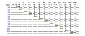
Each output changes between logic HIGH and LOW according to the binary counting sequence. Because each successive output operates at half the frequency of the preceding stage, different outputs can be selected to obtain different flashing rates. The 12-bit counter provides 212, or 4096, possible binary states. The outputs therefore represent different stages of the binary counting sequence.
Generating the Clock Signal
Before using the CD4040B as an LED flasher, a suitable timing or clock signal must be generated. There are several ways to generate a clock signal. A simple method is to use an NE555 timer configured as an astable multivibrator. In this configuration, the 555 timer generates a continuous square-wave signal that can be applied to the clock input of the ripple counter. The clock period and frequency are related by:
T = 1 / f
For example, if a 12-bit counter is used and the desired output frequency at a selected stage is known, the required input clock frequency can be calculated using the frequency-division relationship. For the 12th output:
fQ12 = fclock / 4096
Therefore, if the desired Q12 output frequency is approximately 0.25 Hz, the required clock frequency would be approximately:
fclock = 0.25 × 4096 = 1024 Hz
Simple LED Flasher Circuit
LEDs can be connected to different outputs of the ripple counter. Since each output operates at a different frequency, the LEDs can flash at different rates.
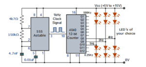
When several outputs are connected to LEDs, different visual effects can be produced, including:
- Sequential flashing
- Chaser effects
- Twinkling effects
- Alternating flashing
- Other decorative lighting patterns
The actual flashing pattern depends on which ripple-counter outputs are selected and how the LEDs are arranged.
Ripple Counter Output
The outputs of the counter can be used to drive loads connected to the output terminals. The source material describes the 4040 outputs as being capable of both sinking and sourcing current. This allows LEDs to be connected in two basic configurations:
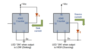
- Current sinking: The load is connected between the positive supply and the counter output.
- Current sourcing: The load is connected between the counter output and ground.
Current Sinking Configuration
In a sinking configuration, the LED is connected between the positive supply rail and a counter output such as Q8. When the output becomes LOW, current flows into the counter output, causing the LED to turn ON.
Current Sourcing Configuration
In a sourcing configuration, the LED is connected between the counter output and ground. When the output becomes HIGH, current flows from the counter output toward ground through the LED, causing the LED to turn ON.
Alternating LED Flasher
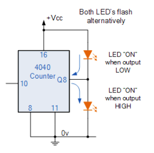
Because a counter output can change between HIGH and LOW, LEDs can be arranged so that two LEDs operate alternately. For example, one LED can be connected in a sinking configuration while another is connected in a sourcing configuration. Depending on the logic state of the selected output, one LED turns ON while the other turns OFF. This produces an alternating flashing effect. When designing the circuit, appropriate current-limiting components should be considered to keep LED current within the safe operating limits of the LEDs and the counter IC.
Using a Transistor Driver for Higher-Power Loads
The output of a ripple counter is suitable for controlling relatively small loads. However, higher-power devices such as motors, relays, and electromagnets generally require more current than a logic IC output should directly provide. In such applications, a transistor can be used as a driver between the counter output and the load. Depending on the required load current, a suitable transistor, Darlington transistor, or power MOSFET can be used as the switching device.
Inductive Loads
Motors, relays, and electromagnets are inductive loads. When their current is interrupted, they can generate a reverse voltage, commonly called back EMF. A freewheeling diode connected across an inductive load can provide a path for the stored energy and help protect the switching transistor from voltage spikes.
LED Current Considerations
LEDs require an appropriate current for proper operation. The actual current depends on the LED type, supply voltage, circuit configuration, and the electrical characteristics of the LED. For reliable circuit operation, the LED current should be limited to an appropriate value rather than assuming that every LED requires the same current. When multiple LEDs are connected, the total load on the counter output should also remain within the manufacturer’s specified output-current limits.
Simple LED Flasher Using NE555 and CD4040B
A basic LED flasher can therefore be constructed using two main functional blocks:
- NE555 Astable Timer: Generates the clock or timing signal.
- CD4040B Ripple Counter: Divides the clock frequency and provides multiple output signals for driving LEDs.
The basic signal flow is:
NE555 Timer → CD4040B Ripple Counter → Selected Counter Outputs → LEDs
The selected counter output determines the flashing frequency of the connected LED.
Using the CD4060 for an LED Flasher
The CD4060B is a 14-bit binary ripple counter that also includes an integrated oscillator section. Because the oscillator is built into the IC, a simple LED flasher circuit can be constructed using the CD4060 with a timing capacitor and resistors. This configuration can eliminate the need for a separate NE555 timer IC because the CD4060 can generate the clock signal internally and divide it through its counter stages.
Advantages of a Ripple Counter LED Flasher
- Simple circuit design
- Useful for learning frequency division
- Multiple output frequencies are available
- Can produce sequential and alternating LED effects
- Requires relatively few components
- Can be expanded using additional counter stages
- Useful for educational and hobby electronics projects
Applications
- LED flashing circuits
- Decorative lighting
- LED chaser circuits
- Sequential lighting displays
- Frequency divider circuits
- Digital electronics experiments
- Timing and control circuits
- Educational electronics projects
Conclusion
A binary ripple counter provides a simple and effective way to build an LED flasher circuit. By cascading divide-by-2 stages, a single clock signal can be converted into multiple lower-frequency signals that can drive LEDs at different rates. The CD4040B 12-bit ripple counter can provide multiple frequency-divided outputs, while an NE555 astable timer can be used to generate the required clock signal. For higher-power loads, transistor or MOSFET drivers can be added between the counter output and the load. Another practical option is the CD4060B, which combines an oscillator with a binary ripple counter, allowing a simple LED flasher to be built with fewer external components.