
Introduction
In the late 1990s, OTDR administrators and the customer community introduced a standardized data technique for storing and analyzing optical fiber information obtained from OTDR testing. The primary objective of this development was to ensure universal compatibility among OTDR devices manufactured by different vendors.
Although some format irregularities were initially identified, all communication issues were resolved over time, enabling cross-utilization between various manufacturers. The standardized OTDR format was officially launched in 2011. This article discusses the working principle, specifications, performance parameters, and types of Optical Time-Domain Reflectometers.
What is OTDR (Optical Time-Domain Reflectometer)?
OTDR stands for Optical Time-Domain Reflectometer. It is an optoelectronic testing instrument used to characterize and analyze optical fibers. This device is the optical equivalent of an electronic time-domain reflectometer.
The primary function of an OTDR is to detect and measure back-scattered or reflected light caused by imperfections, splices, bends, and faults within an optical fiber. In general, an OTDR monitors signal propagation along the fiber link.
OTDRs are also used to analyze splice losses, fiber attenuation, and reflectance. When an optical signal travels through a fiber, partial reflections occur due to faults and refractive index variations, resulting in signal loss. OTDRs help evaluate these losses in optical communication systems.
Working of Optical Time-Domain Reflectometer
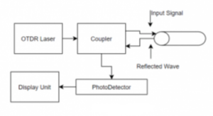
An Optical Time-Domain Reflectometer measures signal loss in an optical fiber by launching a series of optical pulses into the fiber and analyzing the back-scattered light. The working principle of an OTDR is based on Rayleigh scattering and Fresnel reflections. The OTDR consists of a laser light source and a photodetector connected through either an optical coupler or an optical circulator. The fiber under test is connected via a front-panel connector.
The laser generates short, high-intensity optical pulses that are injected into the fiber. When an optical coupler is used, part of the signal may be lost. However, when an optical circulator is used, nearly the entire signal is directed into the fiber, increasing the dynamic range of the OTDR.
As the light travels through the fiber, losses occur due to absorption, Rayleigh scattering, and splices. Reflections also occur at points where there is a change in refractive index. The reflected light travels back to the OTDR, allowing the instrument to identify and locate fiber characteristics and faults. Although circulators improve performance, they increase the cost of the OTDR compared to coupler-based designs.
Optical Time-Domain Reflectometer Specifications
Dead Zone
The dead zone is one of the most important OTDR specifications. It refers to the distance after a strong reflection where the OTDR cannot accurately detect faults or events. This occurs because strong reflected signals deliver more power to the photodetector than back-scattered signals, causing temporary saturation. During the recovery period, the OTDR is unable to detect weaker reflections, resulting in a dead zone.
OTDR Traces
The OTDR trace represents reflected optical power versus distance along the fiber. The horizontal axis represents distance, while the vertical axis represents reflected power level.

- Positive spikes: Caused by Fresnel reflections at fiber joints and connectors.
- Step losses: Indicate splice or connector losses.
- Gradual slope: Caused by Rayleigh scattering due to refractive index variations, which is the primary cause of fiber attenuation.
Performance Parameters of OTDR
The performance of an OTDR is mainly defined by two parameters:
Dynamic Range
Dynamic range is the difference between the back-scattered optical power near the front-end connector and the noise floor at the far end of the fiber. It determines the maximum loss that can be measured in the fiber link.
Measurement Range
The measurement range defines the maximum distance over which the OTDR can accurately analyze the fiber. It depends on pulse width and fiber attenuation.
Types of OTDR
Full-Feature OTDR
These are traditional OTDRs with extensive features and high accuracy. They are generally large, less portable, and used in laboratories. These devices are powered by batteries or AC supply.
Hand-Held OTDR
Hand-held OTDRs are compact, lightweight, and easy to use. They are primarily used for field testing, troubleshooting, and maintenance of fiber networks.
Conclusion
Optical Time-Domain Reflectometers play a vital role in the testing and maintenance of optical communication networks. Selecting the appropriate OTDR based on application requirements ensures accurate fault detection and optimal network performance.


