
Introduction
GSM (Global System for Mobile Communications) uses a combination of FDMA (Frequency Division Multiple Access) and TDMA (Time Division Multiple Access) techniques. In FDMA, the available bandwidth of 25 MHz is divided into 124 carrier frequencies, each spaced 200 kHz apart.
These carrier frequencies are further divided in time using TDMA. This allows multiple users to share the same frequency channel by assigning them different time slots, avoiding interference. A GSM slot is the time allocated to a user, and a GSM burst is the actual transmission that occurs during this time.
- One GSM slot duration = 0.577 ms
- 8 slots form one TDMA frame
- One TDMA frame duration = 4.615 ms
Each TDMA frame forms a basic unit for defining logical channels and contains one physical channel and one burst period.
GSM Slot Structure
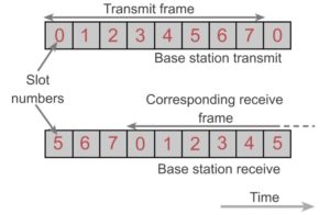
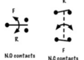
A GSM slot is the smallest time unit assigned to a mobile device. Each slot has a predefined structure to transmit different types of data such as voice, control, and synchronization information. Typically, a GSM slot carries 148 bits of data. There is a time offset between uplink and downlink slots. This ensures that a mobile device does not transmit and receive simultaneously, eliminating the need for complex filters and reducing hardware cost.
What is a GSM Burst?
A GSM burst is the transmission of data within a GSM time slot. Different types of bursts are used depending on the purpose of communication.
Types of GSM Bursts
- Normal Burst (Uplink and Downlink)
- Synchronization Burst
- Frequency Correction Burst
- Random Access Burst
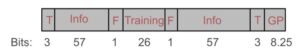
GSM Normal Burst Structure
The normal burst is the most commonly used burst and is used for voice and standard data communication.
- 3 Tail Bits: Used to ramp up transmitter power
- 57 Data Bits: Carry voice or signalling data
- 1 Flag Bit: Indicates type of data (traffic or control)
- 26-bit Training Sequence: Used for synchronization and equalization
- 1 Flag Bit: Indicates data type again
- 57 Data Bits: Additional data transmission
- 3 Tail Bits: Used to ramp down transmitter power
- 8.25-bit Guard Time: Prevents overlap between bursts
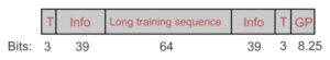
GSM Synchronization Burst
This burst is used for network synchronization, helping mobile devices align with the base station timing.
- 3 Tail Bits
- 9 Information Bits
- 64-bit Training Sequence
- 39 Information Bits
- 3 Tail Bits
- 8.25-bit Guard Interval
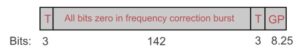
GSM Frequency Correction Burst
This burst is used to correct frequency errors. All bits are set to zero, producing a constant frequency signal with no phase variation.
- 3 Tail Bits
- 142 Zero Bits
- 3 Tail Bits
- 8.25-bit Guard Interval
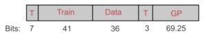
GSM Random Access Burst
This burst is used when a mobile device attempts to connect to the network. It is shorter in data length but includes a longer guard period to accommodate timing uncertainties.
- 7 Tail Bits
- 41 Training Bits
- 36 Data Bits
- 3 Tail Bits
- 69.25-bit Guard Time
Discontinuous Transmission (DTX) in GSM
Discontinuous Transmission (DTX) is a feature used to reduce power consumption and interference by stopping transmission during silent periods in speech. In a typical conversation, a person speaks less than 40% of the time. During silent intervals, transmission is paused to save energy.
A Voice Activity Detector (VAD) is used to detect whether speech is present or not. If speech is incorrectly detected as noise, it may cause clipping. If noise is detected as speech, efficiency is reduced. To avoid complete silence, the system generates comfort noise using a Silence Indication Descriptor (SID).
GSM Frame Structure
GSM organizes data into frames, slots, multi frames, and super frames to ensure proper synchronization and efficient transmission. The frame structure allows both voice data and signaling information to be transmitted in an organized manner It forms the foundation of GSM communication and supports various physical and logical channels used in the system.