• Home
  • About Us
  • Contact Us
Semiconductor for You
  • Home
  • Semiconductor News
  • Technology
    • Automotive
    • Consumer Electronics
    • IoT
    • Lighting
    • Power Management
    • Wireless
    • Personal Electronics
    • Hardware & Software
    • Research
    • Medical Electronics
    • Embedded Design
    • Aerospace & Defence
    • Artificial Intelligence
  • DIY Projects
  • Market
  • Industries
    • Renesas Electronics
  • Knowledge Base
  • Events
  • Tools
    • Resistor Color Code Calculator
No Result
View All Result
Semiconductor for You
No Result
View All Result
Home Knowledge Base

2N2646 Uni Junction Transistor & Its Working

Mrinali Sharma by Mrinali Sharma
August 26, 2022
in Knowledge Base
0
ADVERTISEMENT
  • N2646 is a general-purpose silicon PN Unijunction Transistor that is designed for general-purpose industrial applications.
  • This transistor is made out of n-type semiconductors, with the length of the p-type material controlled to help fix the intrinsic standoff ratio parameter. Emitter, base, and collector are the three terminals on a typical 2n2646 UJT.
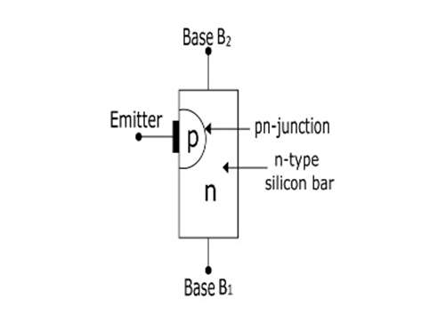
2N2646 Uni Junction Transistor

Pin Configuration

Pin Name Description
1 Base 1 Normally connected to Power
2 Emitter An emitter is used for triggering transistor ON and OFF
3 Base 2 Normally connected to Load

Working

1. When the Emitter is Open

  • When the voltage VBB is applied with the emitter open, a potential gradient is established along the n-type silicon bar.
  • The voltage V1 (between emitter and B1) establishes a reverse bias on the PN-junction.
  • Emitter current is cut off, but a small leakage current flows from B2 to emitter due to minority charge carriers.
When the Emitter is Open
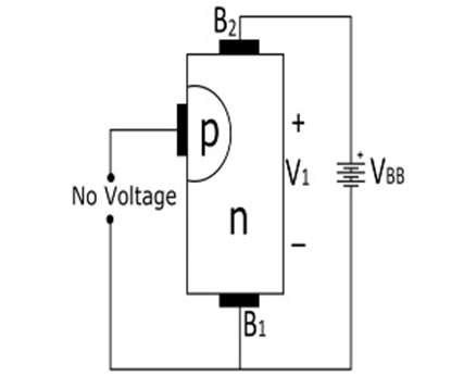
  • Thus, the device is said to be in an OFF state.

2. With Emitter at Positive Potential

  • When a positive voltage is applied at the emitter terminal, the PN-junction will remain reverse biased till the input voltage is less than V1.
  • The PN-junction becomes forward-biased when the input voltage at the emitter exceeds V1.
  • Under this condition, holes are supplied from the p-type region into the n-type bar, due to this saturation of charge carriers occur.
  • The emitter current is limited by the emitter power supply because of this saturation.
With Emitter at Positive Potential
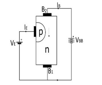
  • Now, the device is conducting, hence said to be in ON state.

Characteristics of 2N2646 Uni Junction Transistor

  • Low Peak Point Current: 5mA (Max).
  • Low Emitter Reverse Current:005mA (Typ).
  • Maximum voltage between two bases (VB2B1): 35V.
  • Maximum emitters reverse voltage (VB2E): 30V.
  • Maximum RMS emitter current (Ie): 50mA.
  • Maximum peak emitter current (Ie): 2A.

Applications of 2N2646 Uni Junction Transistor

  • Timing circuit.
  • Voltage detector.
  • Phase control circuit.
  • General-purpose industrial applications.
Content Protection by DMCA.com
Mrinali Sharma

Mrinali Sharma

Browse by Category

  • Aerospace and Defence
  • Articles
  • Automotive
  • Consumer-Electronics
  • Hardware & Software
  • Interview
  • IoT
  • Knowledge Base
  • Lighting
  • Market
  • personal-electronics
  • Power Management
  • Research
  • Semiconductor Events
  • Semiconductor News
  • Technology
  • Wireless
Semiconductor for You

Semiconductor For You is a resource hub for electronics engineers and industrialist. With its blend of
technology features, news and new product information, Semiconductor For You keeps designers and
managers up to date with the fastest moving industry in the world.

Follow Us

Browse by Category

  • Aerospace and Defence
  • Articles
  • Automotive
  • Consumer-Electronics
  • Hardware & Software
  • Interview
  • IoT
  • Knowledge Base
  • Lighting
  • Market
  • personal-electronics
  • Power Management
  • Research
  • Semiconductor Events
  • Semiconductor News
  • Technology
  • Wireless

Recent News

New SPI Absolute Encoder Supports 9 mm to 15.875 mm Motor Shafts

New SPI Absolute Encoder Supports 9 mm to 15.875 mm Motor Shafts

June 11, 2025
Infineon Secures the Future with 10 Billion Integrity Guard Chips Delivered

Infineon Secures the Future with 10 Billion Integrity Guard Chips Delivered

June 11, 2025
  • About
  • Advertise
  • Privacy & Policy
  • Contact

© 2022 Semiconductor For You

No Result
View All Result
  • Home
  • Semiconductor News
  • Technology
    • IoT
    • Wireless
    • Power Management
    • Automotive
    • Hardware & Software
  • Market
  • Knowledge Base
  • Tools
    • Resistor Color Code Calculator

© 2022 Semiconductor For You