- Because the MPSA42 is an NPN transistor, the collector and emitter will be open (reverse biased) when the base pin is held at the ground and closed (forward biased) when a signal is applied to the base pin. It has a gain value of 30; this value determines the amplification capacity of the transistor; normally, due to its low gain value, MPSA42 will not be used for amplification.
- Because the maximum amount of current that can flow through the Collector pin is 500mA, we cannot use this transistor to drive loads that consume more than 500mA. To bias a transistor, we must supply current to the base pin; this current (IB) should be kept to a maximum of 5mA.
- When fully biased, this transistor can allow up to 500mA to flow across the collector and emitter. This is known as the Saturation Region, and the typical voltage allowed across the Collector-Emitter (V¬CE) or Collector-Base (VCB) may be 300V or 300V, respectively. When the base current is removed, the transistor turns completely off; this is referred to as the Cut-off Region.
How to use MPSA42 Transistor?

ADVERTISEMENT
- The MPSA42 transistor is intended for amplification and high voltage switching. It is, however, mostly used when the load on the output side has a high voltage.
- When this transistor is used as a switch, it operates in two states: saturation and cut-off. In the saturation region, the transistor behaves like a close switch, with current flowing from the collector terminal (C) to the emitter terminal (E), whereas in the cut-off region, the transistor behaves like an open switch, with no current flowing from the collector terminal to the emitter.
- One thing to keep in mind is that the collector current must be 500mA when connected to a load. If the current is greater than this, do not connect to the load; otherwise, the circuit will be damaged.
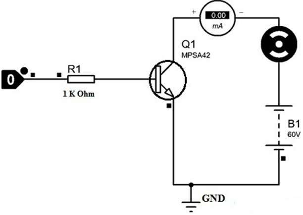
- In this example, a circuit is designed using the MPSA42 transistor to control a motor, with the transistor acting as a switch. This transistor is commonly used in high voltage switching. The following circuit connects an NPN transistor to control a high voltage-based DC motor.
- This resistor value is measured using the formula RB= VBE / IB, where VBE = 5V, IB = 500mA, and RB = 1K. When a 5V DC voltage is applied to the base pin of this transistor via a 1K resistor and the transistor is connected to the GND, the DC motor will turn on.
- Similarly, when 0V is applied to the base terminal of this transistor, there is no current flow, so this transistor does not connect to GND and the DC motor does not operate.
Pin Configuration
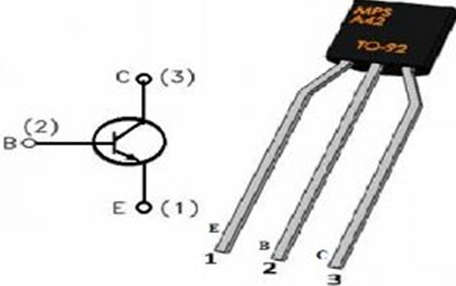
- Pin1 (Emitter): This terminal drains out the current.
- Pin2 (Base): The base terminal controls the transistor biasing.
- Pin3 (Collector): Current supplies throughout this terminal.
Applications of MPSA42 Transistor
- MPSA42 transistor is used in high voltage-based applications like Telephonic, video communications, etc.
- This transistor can also be used for high voltage-based switching.
- If this transistor is used as a switch then it can drive up to 500mA of loads to control LEDs, relays, and medium & high power transistors.
- This transistor can be used as an amplifier in audio-based applications.
- Inverter-based applications.
- Low current-based motors speed control.
- Circuits like UPS, battery chargers, etc.
- Drive LEDs, stepper motors, etc.
- High voltage-based power supplies.
- Audio amplifiers & their stages.
- Controllers of the motor.
- To switch different loads which work with high voltage.
- Drive LEDs that operate with high power.
- High peak voltage-based loads can be controlled.
- Drive stepper motors with high voltage.
- Low current motors speed can be controlled.