- The AC circuit is commonly known as an alternating current.
- Impedance is the opposition to the current flowing around the circuit.
- Impedance is a value given in Ohms i.e. the combined effect of the circuit current limiting components within it, such as Resistance (R), Inductance (L), and Capacitance (C).
- In a DC circuit, the opposition to current flow is called Resistance, but in an AC circuit, impedance is the result of both the circuit’s resistive (R) and reactive (X) components.
- In a DC circuit, the amount of electrical resistance present is denoted by the letter “R” and for an alternating AC circuit, the letter “Z” is used to represent the opposition to current flow.
- We observe that impedance (Z) is the combined effect of the total values of the resistance (R) and the reactance (X) present within an AC circuit.
- However, the impedance depends on the frequency and therefore has a phase angle associated with it.
- The reactance phase angle, either inductive or capacitive, is always 90o out-of-phase with the resistive component, so the circuit’s resistive and reactive values cannot be simply added together arithmetically to give the circuit total impedance value. That is R + X does not equal Z.
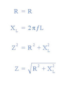
- The resistance is directly equal to their impedance, (R = Z) because the resistors do not change their value with frequency and therefore have no reactance.
- Therefore the resistors have no phase angle, so the voltage across them and the current flowing through them will always be “in-phase”.
- Although, reactance in the form of inductive reactance, (XL) or capacitive reactance, (XC) does change with frequency, causing a circuit’s impedance value to vary as the supply frequency varies.
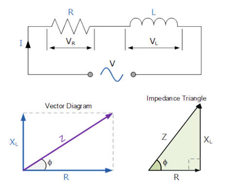
Resistance and Inductive Reactance
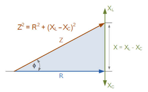
- The following right-angled graphs show how resistance and reactance are combined with the hypotenuse (longest side) of the triangle representing the complex impedance of the circuit.
- We can use Pythagoras’s theorem and associated equations to relate the two sides of the right-angled triangle representing resistance and inductive reactance to the length of the third side being the hypotenuse for a three-sided right-angled triangle.
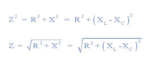
- Pythagoras’s theorem is explained in terms of impedance, resistance, and reactance as being:
Z2 = R2 + X2
That is:
(Impedance)2 = (Resistance)2 + (Reactance)2 - Thus the “Z” is the resulting vector sum of the resistance vector (R) and the reactance vector (XL) and is a positive slope as shown.
Impedance of an RL Circuit
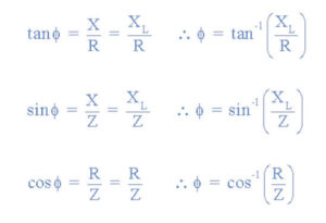
Phase Angle of an RL Circuit
The angle in degrees between the two vectors is called phase angle (φ).
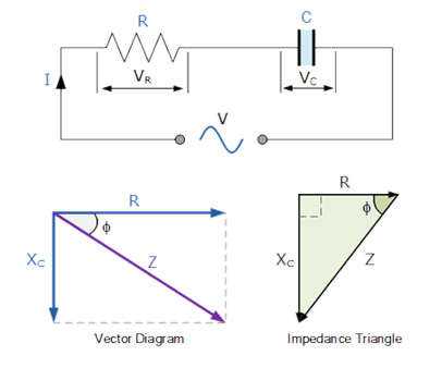
Resistance and Capacitive Reactance
- For resistance and capacitive reactance, the right-angled graph uses and combined with the hypotenuse (longest side) of the triangle representing the complex impedance of the circuit.
- Make sure that for a capacitor “Z” is the vector sum of the resistance vector (R) and the reactance vector (XC).
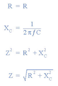
- Again using Pythagoras’s theorem and equations we can relate the two sides of the right-angled triangle representing resistance and capacitive reactance to the hypotenuse which is the complex impedance.
- In terms of impedance, resistance and reactance the Pythagoras theorem is used.
Impedance of an RC Circuit
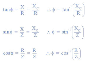
- The angle in degrees between the impedance vector and the resistance vector is called the tangent of the phase angle (φ).
- The phase angle is equal to the reactance divided by the resistance as shown.
Phase Angle of an RC Circuit
Impedance of an RLC Circuit
- For resistance and reactance (inductive and capacitive) the vector diagram can be used and combined to form impedance.
- The sum of the inductive reactance, XL, and the capacitive reactance, XC is the combined reactance of the series circuit as shown below.
- X = XL + (-XC) = XL – XC
- Which gives