
Introduction
Several AC bridges are used for measuring inductance and quality factor (Q). Hay’s bridge is suitable for measuring high-Q inductors (Q > 10), Maxwell’s bridge for medium-Q inductors (Q = 1 to 10), and Anderson’s bridge is effective for measuring inductance ranging from a few microhenry to several henry. However, all these bridges have a limited measurement range. To overcome this limitation, Owen’s Bridge is used because it can measure a wider range of inductors accurately.
What is Owen’s Bridge?
Owen’s Bridge is an AC bridge used to measure an unknown inductance in terms of a known standard capacitance. Like other AC bridges, it uses a combination of standard capacitors, inductors, and variable resistors excited by an AC source.
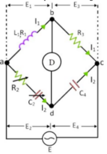
The bridge has four arms: ab, bc, cd, and da:
- Arm ab: Contains the unknown inductor L1 with resistance.
- Arm bc: Contains a pure resistor.
- Arm cd: Contains a fixed capacitor C4.
- Arm ad: Contains a variable resistor R2 and variable capacitor C2 in series.
The unknown inductance L1 is compared with the known capacitance C4. Balance is achieved by adjusting R2 and C2 independently. At balance, no current flows through the detector, and points b and c are at the same potential.
Theory of Owen’s Bridge
An AC supply is connected between points a and c. Arm ab contains the unknown inductor having resistance r1 and inductance l1. Arm bc contains a pure resistance r3. Arm cd contains a capacitor C4, and arm ad contains variable components R2 and C2.
At balance, AC bridge theory states:
Z1 × Z4 = Z2 × Z3
Substituting impedances and separating real and imaginary parts gives the balance equations for the unknown inductance L1 and resistance r1.
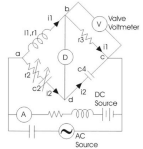
Incremental Inductance Measurement
In a modified Owen’s Bridge, a valve voltmeter is connected across resistor r3. The bridge is fed from both AC and DC sources in parallel:
- The inductor isolates the DC source from AC.
- The capacitor prevents DC from entering the AC source.
- An ammeter measures the DC component.
- The voltmeter measures the AC component.
At balance, the incremental inductance is:
l1 = R2 × R3 × C4
Incremental Permeability
Incremental permeability is given by:
μ = (l1 × l) / (N² × A)
where:
- N = Number of turns
- A = Cross-sectional area of flux path
- l = Length of flux path
- l1 = Incremental inductance
Phasor Diagram Explanation
Let the voltage drops across arms ab, bc, cd, and ad be e1, e3, e4, and e2.
At balance, e1 = e2.
Current i1, flowing through the inductive arm, lags the most and is taken as the reference for drawing the phasor diagram.

The inductive drop is perpendicular to i1, while the capacitive drop is perpendicular to i2. The sum of all voltage drops forms the complete phasor shown in the bridge analysis.
Advantages of Owen’s Bridge
- Two independent balance conditions make adjustment easy because both R2 and C2 are in the same arm.
- Balance equations are simple and independent of frequency.
- Capable of measuring a wide range of inductances accurately.
Disadvantages of Owen’s Bridge
- Uses a variable standard capacitor, which is expensive and typically accurate only up to 1%.
- For high-Q measurements, the required capacitor value becomes large, increasing cost and size.