Introduction
A summing amplifier is an operational amplifier (op-amp) circuit used to add multiple input voltages and produce a single output voltage proportional to their sum. The process of adding or subtracting voltages using an operational amplifier is known as voltage summation.
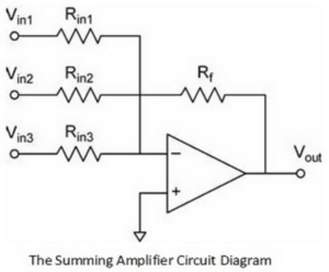
A summing amplifier is commonly derived from the inverting operational amplifier, where multiple input signals are connected to the inverting terminal through separate resistors.
Working of Summing Amplifier
Consider three input voltages:
- V1 connected through resistor R1
- V2 connected through resistor R2
- V3 connected through resistor R3
These voltages are applied to the inverting terminal of the operational amplifier. Two important golden rules of an operational amplifier are:
- No current flows into the input terminals of the op-amp.
- The voltage difference between the inverting and non-inverting terminals is zero.
Since the non-inverting terminal is connected to ground (0V), the inverting terminal acts as a virtual ground or virtual earth.
Current Relationship in Summing Amplifier
The total feedback current is equal to the sum of all input currents:
:contentReference[oaicite:0]{index=0}
Using Ohm’s Law, the output voltage equation becomes:
:contentReference[oaicite:1]{index=1}
Therefore, the output voltage of the summing amplifier is:
:contentReference[oaicite:2]{index=2}
Equal Input Resistor Condition
If all input resistors have the same value (R), the equation simplifies to:
:contentReference[oaicite:3]{index=3}
When the feedback resistor and all input resistors are equal:
:contentReference[oaicite:4]{index=4}
In this condition, the gain of the summing amplifier becomes equal to 1.
Non-Inverting Summing Amplifier
Although summing amplifiers are generally designed using the inverting amplifier configuration, they can also be implemented using a non-inverting amplifier. In a non-inverting summing amplifier, the input voltages are connected to the non-inverting terminal through resistors. The amplifier then produces an output proportional to the sum of the input voltages.
Applications of Summing Amplifier
1. Audio Mixer Circuits
Summing amplifiers are widely used in audio mixers to combine signals from multiple audio channels into a single output signal. Each input channel can be controlled independently without affecting the overall output.
2. Digital-to-Analog Converter (DAC)
Summing amplifiers are commonly used in Digital-to-Analog Converters (DACs). For example, an 8-bit DAC uses 8 input signals where each input represents a binary logic level (0 or 1). The input resistors are selected in binary-weighted values, usually in powers of two. The summing amplifier converts these binary inputs into a proportional analog output voltage.
Advantages of Summing Amplifier
- Can combine multiple input signals into one output
- Provides accurate analog signal processing
- Simple circuit design using operational amplifiers
- Widely used in audio and communication systems
Conclusion
A summing amplifier is an important operational amplifier circuit used for adding multiple input voltages. It plays a major role in analog signal processing, audio mixing systems, and digital-to-analog converters.