What is a Differential Amplifier?
A differential amplifier is an electronic amplifier that amplifies the difference between two input voltages while rejecting any voltage that is common to both inputs. It is also known as a difference amplifier or op-amp subtractor. A differential amplifier is an analog circuit with:
- Two input terminals
- One output terminal

The output voltage is ideally proportional to the difference between the two input voltages.
Differential Amplifier Formula
The output voltage of a differential amplifier is given by:
:contentReference[oaicite:0]{index=0}
Where:
- Vo = Output voltage
- Ad = Differential gain
- V1 = Input voltage at the inverting terminal
- V2 = Input voltage at the non-inverting terminal
BJT Differential Amplifier Circuit
A BJT differential amplifier consists of:
- Two Bipolar Junction Transistors (BJTs) — Q1 and Q2
- Two collector resistors — RC1 and RC2
- One common emitter resistor — RE
- Positive power supply — VCC
- Negative power supply — VEE
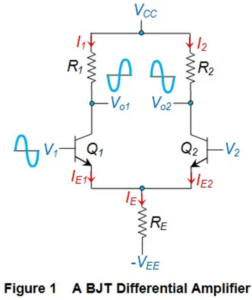 The input signals are applied to the bases of the transistors, and the output is obtained from their collector terminals.
Working of Differential Amplifier
Suppose a sinusoidal signal is applied to transistor Q1.
As the input voltage at Q1 increases:
- The transistor conducts more heavily
- The collector current IC1 increases
- The voltage drop across collector resistor RC1 increases
- The output voltage VO1 decreases
At the same time:
- The emitter current increases
- The voltage drop across emitter resistor RE increases
- The emitter terminals move toward a positive potential
- The base-emitter voltage of Q2 decreases
As a result:
- The collector current IC2 decreases
- The voltage drop across RC2 decreases
- The output voltage VO2 increases
Thus, the signal appearing at the collector of Q2 is amplified and phase-shifted by 180° compared to the signal at Q1.
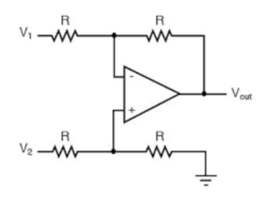
Differential Op-Amp
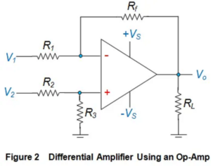
A differential amplifier can also be implemented using an operational amplifier (Op-Amp). In this configuration, input signals are applied to both the inverting and non-inverting terminals of the op-amp. The output voltage produced is proportional to the difference between the two input voltages. Therefore, the differential amplifier acts as a subtractor circuit by subtracting one input signal from the other.
Construction of Differential Amplifier
A differential amplifier can be constructed using:
- Bipolar Junction Transistors (BJTs)
- Field Effect Transistors (FETs)
- Operational Amplifiers (Op-Amps)
Circuit Features of Differential Amplifier
The differential amplifier circuit contains:
- Two input terminals
- Two output terminals
- Two matched transistors (Q1 and Q2)
- Common emitter resistor RE
- Common positive supply VCC
- Common negative supply VEE
Ideally, both transistors should have identical characteristics for proper differential operation.
Configurations of Differential Amplifier
There are four main configurations of a differential amplifier:
1. Dual Input Balanced Output
In this configuration:
- Two input signals are applied
- Output is taken from both transistors
2. Dual Input Unbalanced Output
In this configuration:
- Two input signals are applied
- Output is taken from only one transistor
3. Single Input Balanced Output
In this configuration:
- Only one input signal is applied
- Outputs are taken from both transistors
4. Single Input Unbalanced Output
In this configuration:
- Only one input signal is applied
- Output is taken from only one transistor
Applications of Differential Amplifier
- Operational amplifier input stages
- Noise reduction circuits
- Signal conditioning systems
- Instrumentation amplifiers
- Communication systems
- Analog signal processing
Advantages of Differential Amplifier
- Excellent noise rejection capability
- High voltage gain
- Improved signal stability
- Can amplify very small signals accurately
Conclusion
A differential amplifier is one of the most important analog circuits used in electronics. It amplifies the difference between two signals while rejecting common unwanted signals and noise. Differential amplifiers are widely used in operational amplifiers, communication systems, and signal processing applications.