

The Doherty amplifier is used in many areas where high-efficiency RF power amplifiers are needed for high peak-to-average power ratio uses.
- The Doherty amplifier was invented by William H. Doherty of Bell Telephone Laboratories Inc in 1936.
- Doherty amplifier is a modified class B radio frequency amplifier.
- Although conventional class B amplifiers can clip on high input-signal levels, the Doherty power amplifier can accommodate signals with high peak-to-average power ratios by using two amplifier circuits within the one overall amplifier to accommodate the different signal levels.
- Thus, the amplifier achieves a high level of linearity while retaining good power efficiency.
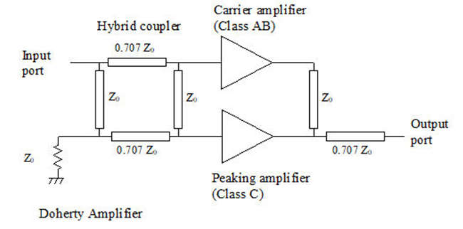
- The above figure shows the block diagram of the Doherty amplifier. As shown in the figure, the Doherty amplifier consists of a carrier amplifier and a peaking amplifier.
- Carrier amplifier is usually class AB type whereas preamplifier is usually class C type.
- As shown figure, it uses an RF splitter at the input which creates two signals viz. -90 degree shifted (top) and -180 degree phase shifted (bottom).
- 90 degrees out of the phase of the two signal outputs of amplifiers.
- This will create more issues. Hence quarter wave impedance transformer is used in a top path as shown at the output.
- This will conduct both signals to the same phase. At the output, both of these signals are added.
- This combined amplified RF output signal is passed through a quarter wave impedance transformer to bring it back to the normal phase.
- The use of both class AB amplifiers and Class C amplifier in Doherty architecture restores signal fidelity at the output.
Types of Doherty Amplifier
Symmetric Doherty Amplifier:
- This is the simpler method for designing the RF circuit of a Doherty amplifier. Although it has a circuit with two identical RF amplifiers, it does not nearly match the second type’s performance.
Asymmetric Doherty Amplifier:
- The most popular format for the RF circuit design of this kind of amplifier is the asymmetric Doherty. Within the whole block, there are two distinct RF amplifiers. The peaking amplifier in this method can handle more power. This implies that it can handle the signal peaks, freeing up the lower power amplifier to handle the lower signal levels more effectively. This method makes it possible to obtain significantly higher performance levels.
Digital Doherty Amplifier:
- Doherty amplifiers have traditionally been designed using analog approaches, but due to the various bias schemes and phase offsets utilized for the various amplifiers, the bandwidth and efficiency are constrained. Digital engineering approaches have been used to develop Doherty amplifiers.
Advantages of Doherty Amplifier
- Enables higher efficiency levels to be achieved.
- Technology is not as complicated as envelope tracking which also improves RF amplifier efficiency.
Disadvantages of Doherty Amplifier
- Difficult to maintain phase shifts of splitters over a wide bandwidth and therefore Doherty amplifier can only be used over limited bandwidth.
- Higher cost than a single amplifier.
- Design is not easy to undertake and obtain optimum performance.