• Home
  • About Us
  • Contact Us
Semiconductor for You
  • Home
  • Semiconductor News
  • Technology
    • Automotive
    • Consumer Electronics
    • IoT
    • Lighting
    • Power Management
    • Wireless
    • Personal Electronics
    • Hardware & Software
    • Research
    • Medical Electronics
    • Embedded Design
    • Aerospace & Defence
    • Artificial Intelligence
  • DIY Projects
  • Market
  • Industries
    • Renesas Electronics
  • Knowledge Base
  • Events
  • Tools
    • Resistor Color Code Calculator
No Result
View All Result
Semiconductor for You
No Result
View All Result
Home Knowledge Base

Basic of Yagi Antenna / Yagi-Uda Aerial : Working and Applications

Nikita Bisen by Nikita Bisen
September 13, 2022
in Knowledge Base
0
ADVERTISEMENT

The Yagi antenna or aerial sometimes called the Yagi-Uda antenna is widely used for broadcast, domestic and commercial radio communications applications where gain and directivity are required from an RF antenna design.

  • The yagi uda antenna was invented in 1926 by Shintaro Uda of Tohoku Imperial University, Japan, with a lesser role played by his colleague Hidetsugu Yagi.
  • It is a directional antenna consisting of two or more parallel resonant antenna elements in an end-fire array these elements are most often metal rods acting as half-wave dipoles.
  • It consists of a single driven element connected to a radio transmitter or receiver through a transmission line.
Yagi Antenna

Working of Yagi Antenna

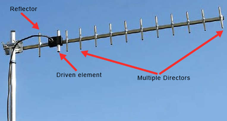
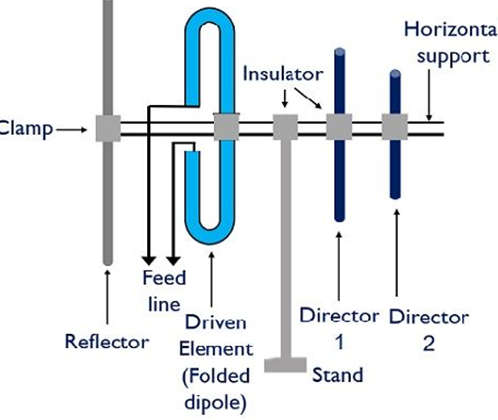
  • In the yagi uda antenna, there are 3 major elements are used that are generally a half-wave folded dipole, a reflector, and directors.
  • The yagi uda antenna structure contains one driven element and a reflector while directors can be more than one.
  • The yagi uda antenna arrangement is said to be an array of active and parasitic elements.
  • The metallic rod acts as the active element as external feeding is provided to it using transmission lines in the dipole.
  • The parasitic elements of the structure are the reflector and director.
  • The parasitic elements are also metallic rods placed parallel in the line of sight orientation w.r.t the driven element.
  • Although, when the dipole is excited using a transmission line then the current flows through the driven element and induces voltages in the parasitic elements.
  • The elements are mounted on a center rod, that acts as horizontal support.
  • The figure below represents the structure of the Yagi-Uda antenna.
Structure of Yagi-Uda Antenna

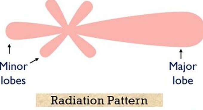
Radiation Pattern of Yagi-Uda Antenna

  • The given below diagram shows the radiation pattern of the Yagi-Uda antenna.

Advantages of Yagi Antenna

  • High gain is achieved.
  • The high directivity is achieved.
  • Ease of handling and maintenance.
  • Less amount of power is wasted.
  • Broader coverage of frequencies.

Disadvantages of Yagi Antenna

  • Prone to noise.
  • Prone to atmospheric effects.

Applications of Yagi Antenna

  • Mostly used for TV reception.
  • Used where a single-frequency application is needed.
Content Protection by DMCA.com
Nikita Bisen

Nikita Bisen

Browse by Category

  • Aerospace and Defence
  • Articles
  • Automotive
  • Consumer-Electronics
  • Hardware & Software
  • Interview
  • IoT
  • Knowledge Base
  • Lighting
  • Market
  • personal-electronics
  • Power Management
  • Research
  • Semiconductor Events
  • Semiconductor News
  • Technology
  • Wireless
Semiconductor for You

Semiconductor For You is a resource hub for electronics engineers and industrialist. With its blend of
technology features, news and new product information, Semiconductor For You keeps designers and
managers up to date with the fastest moving industry in the world.

Follow Us

Browse by Category

  • Aerospace and Defence
  • Articles
  • Automotive
  • Consumer-Electronics
  • Hardware & Software
  • Interview
  • IoT
  • Knowledge Base
  • Lighting
  • Market
  • personal-electronics
  • Power Management
  • Research
  • Semiconductor Events
  • Semiconductor News
  • Technology
  • Wireless

Recent News

TME, DC power connectors from Amphenol GEC

TME, DC power connectors from Amphenol GEC

June 27, 2025
Analog Semiconductors Poised to Cross USD 100 Billion by 2032

Analog Semiconductors Poised to Cross USD 100 Billion by 2032

June 26, 2025
  • About
  • Advertise
  • Privacy & Policy
  • Contact

© 2022 Semiconductor For You

No Result
View All Result
  • Home
  • Semiconductor News
  • Technology
    • IoT
    • Wireless
    • Power Management
    • Automotive
    • Hardware & Software
  • Market
  • Knowledge Base
  • Tools
    • Resistor Color Code Calculator

© 2022 Semiconductor For You