- A Triac is a medium- to high-power semi-latching solid-state AC power switch that can be controlled. This two-part article explains how it works and shows various applications.
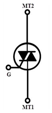
- A Triac is a three-terminal (MT1, gate, and MT2) solid-state thyristor that operates like a pair of SCRs wired in inverse parallel and controlled by a single gate terminal. It can conduct current in either direction between its MT1 and MT2 terminals and can thus be used to control alternating currents directly. It can be triggered by either positive or negative gate currents, regardless of MT2 current polarity, and thus has four possible triggering modes or ‘quadrants,’ denoted as follows:
I+ Mode = MT2 current +ve, gate current +ve
I- Mode = MT2 current +ve, gate current -ve
III+ Mode = MT2 current -ve, gate current +ve
III+ Mode = MT2 current -ve, gate current -ve - When the MT2 and gate currents are both of the same polarity (either both positive or both negative), the trigger current sensitivity is greatest, and is usually about half as great when they are of opposite polarity.
I-V Characteristics Curves
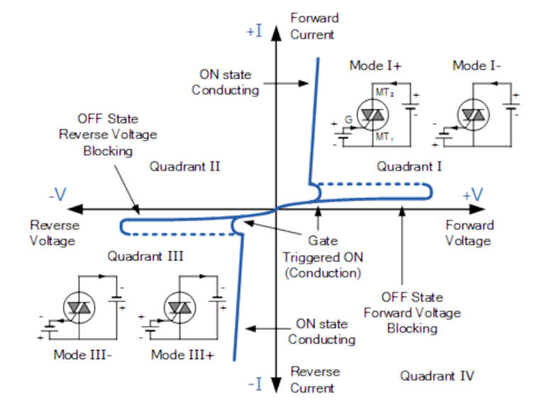
- A positive gate current, labeled above as mode +, usually triggers the triac into conduction in Quadrant I. It can, however, be triggered by a negative gate current, mode -. Similarly, in Quadrant, triggering with a negative gate current, -G, is also common, as are modes – and +. Modes – and +, on the other hand, are less sensitive configurations that require a higher gate current to trigger than the more common Triac triggering modes of + and -.
- In addition, triacs, like silicon-controlled rectifiers (SCRs), require a minimum holding current IH to maintain conduction at the waveform’s cross-over point. Even though the two thyristors are combined into a single device, they still exhibit individual electrical characteristics such as different breakdown voltages, holding currents, and trigger voltage levels, just like a single SCR device.
Triac Technology
- The triac can be thought of as two thyristors or SCRs connected back to back to accommodate both halves of an AC waveform cycle. Because it is a single device, it has significant advantages, especially for domestic products where cost is critical.
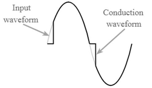
- When a trigger is applied to the gate, the triac turns on and remains to conduct until the voltage across the device’s anodes or main terminals falls below a certain value – nominally when the supply voltage falls to nearly zero. This condition occurs when an alternating waveform crosses the zero voltage line, and the triac can control each half waveform as a result.
Basic Triac Switching Circuit
- The circuit below shows a simple DC-triggered Triac power switching circuit.
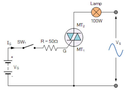
- With switch SW1 open, no current flows into the triac’s Gate, and the lamp is thus “OFF.” When SW1 is closed, gate current is applied to the triac from the battery supply VG via resistor R, driving the triac into full conduction and drawing full power from the sinusoidal supply.
- Because the battery supplies a positive Gate current to the triac whenever switch SW1 is closed, the triac is constantly gated in modes I+ and + regardless of terminal MT2 polarity.
- The problem with this simple triac switching circuit is that we would need an additional positive or negative Gate supply to activate the triac. However, we can also use the actual AC supply voltage as the gate triggering voltage to trigger the Triac. Consider the following circuit.
Issues with Triac Circuits & the Solutions
When using TRIAC circuits, it is critical to understand the most common problems and how to solve them. Some of the drawbacks of using TRIAC circuits are as follows.
- Rate Effect: This effect refers to the TRIAC turning on unintentionally as a result of a sudden change in voltage across its main terminals. The problem is solved by connecting the main terminals with a resistor-capacitor (RC) snubber circuit.
- Backlash Effect: Backlash occurs in phase control circuits when the resistance is set to the maximum to reduce the power levels of the connected device to the lowest possible level. The effect is caused by the TRIAC’s inherent capacitance across its load terminals not having a discharge path, which prevents the connected device from turning on. The solution is to connect a high-value resistor in series with the DIAC or a capacitor between the gate and main terminals to provide a discharge path.
- Non-Symmetrical Firing: This problem occurs in phase control circuits because TRIACs have different turn-on voltages for each direction. The TRIAC’s electromagnetic radiation profile suffers as a result of this design. This problem is solved by connecting a DIAC to the TRIAC’s gate, which evens out the TRIAC’s firing characteristics.
- Harmonic Filtering: Because the TRIAC activates when the voltage across its terminals is greater than zero, it generates harmonics that make it unsuitable for use in sensitive electronic equipment such as wireless communications circuitry. The use of a harmonic filter reduces electromagnetic interference.