• Home
  • About Us
  • Contact Us
Semiconductor for You
  • Home
  • Semiconductor News
  • Technology
    • Automotive
    • Consumer Electronics
    • IoT
    • Lighting
    • Power Management
    • Wireless
    • Personal Electronics
    • Hardware & Software
    • Research
    • Medical Electronics
    • Embedded Design
    • Aerospace & Defence
    • Artificial Intelligence
  • DIY Projects
  • Market
  • Industries
    • Renesas Electronics
  • Knowledge Base
  • Events
  • Tools
    • Resistor Color Code Calculator
No Result
View All Result
Semiconductor for You
No Result
View All Result
Home Knowledge Base

BCD Counter Circuit : Truth Table and Its Applications

Bhushan Chaudhary by Bhushan Chaudhary
September 22, 2022
in Knowledge Base
0
  • A BCD counter is a 4-bit binary counter that counts from 0 to a predetermined count using a clock signal. When the count reaches the predetermined value, it resets all of the flip-flops and begins counting again from 0. This type of counter is built with four JK flip-flops and counts from 0 to 9, with the result represented digitally. It resets and restarts after reaching the count of 9 (1001).
  • A decade counter is so named because it counts ten distinct combinations of the applied input. In binary format, a BCD counter counts 0, 1, 2, 3, 4, 5, 6, 7, 8, 9, 10 and many other values. A four-bit decade counter acts as a BCD counter by skipping any 6 of the 24 outputs. The 74LS90, an asynchronous decade counter, is the most common implementation of this counter.
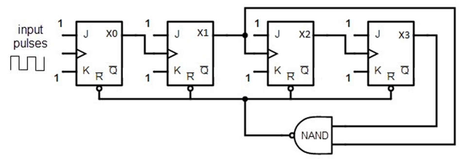
  • A BCD counter built with a JK flip flop is shown below. The J and K terminal outputs are connected to logic ‘1’. Except for the last flip flop, the clock signal’s input in each flip flop is connected to the next flip flop. For all flip-flops, the NAND gate output is connected in parallel to the CLR signal.

BCD or Decade Counter Circuit

BCD Decade Counter Circuit
  • When the decade counter is in REST mode, the count equals ‘0,’ which is 0000 in binary, and this is the beginning of the counter cycle. When a clock signal is connected to the circuit as an input, the circuit begins to count the binary digits in sequence. The initial clock pulse can count to 9 digits, or up to 1001. The count then increases to 10 with the arrival of the next clock pulse, which is 1010.
  • According to the image above, ports X1 and X3 will be high. In the case of high inputs, the NAND gate’s output is at a low position. This output is then connected as an input to the CLR signal, which resets all of the flip-flop stages in the BCD counter. This means that the pulse count from 1001 will reset and begin from ‘0000’.

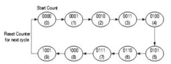
Truth Table and State Diagram of Decade Counter

  • The decade counter’s truth table describes the counting functionality. It represents the circuit’s count in decimals for input pulses. When the circuit count is 10, the output of the NAND gate is ‘0,’ which means 1010. This count is then decoded using the NAND gate inputs X1 and X3. When the count number reaches ’10,’ the NAND gate flips from ‘1’ to ‘0,’ resetting all the flip-flops.


Input Pulses/Clock Pulses QD QC QB QA
0 0 0 0 0(Resets)
1 0 0 0 1
2 0 0 1 0
3 0 0 1 1
4 0 1 0 0
5 0 1 0 1
6 0 1 1 0
7 0 1 1 1
8 1 0 0 0
9 1 0 0 1
  • The operation of the decade counter is explained in four stages in the circuit diagram, with each stage containing a flip flop. As a result, the circuits are capable of counting 16 states (i.e. 16 bits), but only 10 of them are used. The circuit counts from ‘0’ to ‘9,’ and then the NAND gate resets the circuits and begins counting again from ‘0,’ which is 0000. In this manner, many counters can be linked in series to count up to the required number.

  • The number that the BCD circuit can count is referred to as “Modulus,” also known as “Mod”. When a counter automatically resets after counting ‘n’ bits, it is referred to as a Mod-n counter, where ‘n’ is an integer. The Mod counter has a range of ‘0’ to ‘2n – 1’. There are numerous types of counters, including Mod 4, Mod 8, Mod 5, and Mod 16 counters, among others.

74LS90 Decade Counter

  • We use the IC name 74LS90 to solve this problem. The IC includes two MOD counters. The first is a MOD 2 counter, and the second is a MOD 5 counter. The counter begins counting from 0000 to 1001, then resets the value. The automatic reset causes the counter to begin at 0 and end at 9. We have four reset pins on the IC that we can use to enable the counter by activating specific two pins. The IC is TTL-based and thus compatible with other TTL-based counters and ICs.
74LS90 Decade Counter
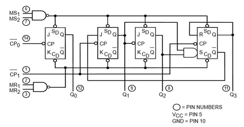
  • The operation of the 7490 will be explained in this section. The internal structure of the IC consists of four flip-flops, the first of which serves as MOD 2 and the other three as MOD 5. The output state will be changed by using the two clock pins. The reset pins are controlled by an AND gate.
  •  The IC has four reset pins, two clock pins, and four output pins. Before we can use the IC, we must first understand the reset pins. The output will be controlled by these four reset pins. These four reset pins will generate multiple 16 combinations, but some of them will produce fixed output. The table is shown below.
MR1 (R4) MR2 (R2) MS1 (R2) MS1 (R1) QD QC QB QA
H H L X L L L L
H H X L L L L L
X X H H H L L H
L X L X COUNT – – –
X L X L COUNT – – –
L X X L COUNT – – –
X L L X COUNT – – –
  • To keep MOD 2 and MOD 5 in sequence, connect the second clock pin (Pin 1) to the LSB of the IC. The clock input signal to the IC will be provided by the first clock pin (Pin 14). The output will be affected as the state changes from HIGH to LOW. However, keep in mind the concept of the reset pins; otherwise, the IC will output some random value or no output. The complete functional circuit is shown here. When we give the pulse, the IC will output the result in binary form. Every binary form corresponds to a decimal number.

Applications of BCD Counter Circuit

  • Clock circuits.
  • Frequency dividers.
  • Frequency counting circuits.
  • State machines.
  • Sequencers.
  • Clock division.
  • CMOS low power circuits.
  • Integrated oscillators.
  • Clock generation.
  • Used as inputs compatible with TTL etc.
Content Protection by DMCA.com
Bhushan Chaudhary

Bhushan Chaudhary

Browse by Category

  • Aerospace and Defence
  • Articles
  • Automotive
  • Consumer-Electronics
  • Hardware & Software
  • Interview
  • IoT
  • Knowledge Base
  • Lighting
  • Market
  • personal-electronics
  • Power Management
  • Research
  • Semiconductor Events
  • Semiconductor News
  • Technology
  • Wireless
Semiconductor for You

Semiconductor For You is a resource hub for electronics engineers and industrialist. With its blend of
technology features, news and new product information, Semiconductor For You keeps designers and
managers up to date with the fastest moving industry in the world.

Follow Us

Browse by Category

  • Aerospace and Defence
  • Articles
  • Automotive
  • Consumer-Electronics
  • Hardware & Software
  • Interview
  • IoT
  • Knowledge Base
  • Lighting
  • Market
  • personal-electronics
  • Power Management
  • Research
  • Semiconductor Events
  • Semiconductor News
  • Technology
  • Wireless

Recent News

Sentry Enterprises and Infineon collaborate to fuel biometric access control and cold storage crypto wallet platforms

Sentry Enterprises and Infineon collaborate to fuel biometric access control and cold storage crypto wallet platforms

January 26, 2023
Renesas Introduces New Gate Driver IC for IGBTs and SiC MOSFETs Driving EV Inverters

Renesas Introduces New Gate Driver IC for IGBTs and SiC MOSFETs Driving EV Inverters

January 26, 2023
  • About
  • Advertise
  • Privacy & Policy
  • Contact

© 2022 Semiconductor For You

No Result
View All Result
  • Home
  • Semiconductor News
  • Technology
    • IoT
    • Wireless
    • Power Management
    • Automotive
    • Hardware & Software
  • Market
  • Knowledge Base
  • Tools
    • Resistor Color Code Calculator

© 2022 Semiconductor For You

We use cookies on our website to give you the most relevant experience by remembering your preferences and repeat visits. By clicking “Accept”, you consent to the use of ALL the cookies.
Cookie settingsACCEPT
Manage consent

Privacy Overview

This website uses cookies to improve your experience while you navigate through the website. Out of these, the cookies that are categorized as necessary are stored on your browser as they are essential for the working of basic functionalities of the website. We also use third-party cookies that help us analyze and understand how you use this website. These cookies will be stored in your browser only with your consent. You also have the option to opt-out of these cookies. But opting out of some of these cookies may affect your browsing experience.
Necessary
Always Enabled
Necessary cookies are absolutely essential for the website to function properly. These cookies ensure basic functionalities and security features of the website, anonymously.
CookieDurationDescription
cookielawinfo-checbox-analytics11 monthsThis cookie is set by GDPR Cookie Consent plugin. The cookie is used to store the user consent for the cookies in the category "Analytics".
cookielawinfo-checbox-functional11 monthsThe cookie is set by GDPR cookie consent to record the user consent for the cookies in the category "Functional".
cookielawinfo-checbox-others11 monthsThis cookie is set by GDPR Cookie Consent plugin. The cookie is used to store the user consent for the cookies in the category "Other.
cookielawinfo-checkbox-necessary11 monthsThis cookie is set by GDPR Cookie Consent plugin. The cookies is used to store the user consent for the cookies in the category "Necessary".
cookielawinfo-checkbox-performance11 monthsThis cookie is set by GDPR Cookie Consent plugin. The cookie is used to store the user consent for the cookies in the category "Performance".
viewed_cookie_policy11 monthsThe cookie is set by the GDPR Cookie Consent plugin and is used to store whether or not user has consented to the use of cookies. It does not store any personal data.
Functional
Functional cookies help to perform certain functionalities like sharing the content of the website on social media platforms, collect feedbacks, and other third-party features.
Performance
Performance cookies are used to understand and analyze the key performance indexes of the website which helps in delivering a better user experience for the visitors.
Analytics
Analytical cookies are used to understand how visitors interact with the website. These cookies help provide information on metrics the number of visitors, bounce rate, traffic source, etc.
Advertisement
Advertisement cookies are used to provide visitors with relevant ads and marketing campaigns. These cookies track visitors across websites and collect information to provide customized ads.
Others
Other uncategorized cookies are those that are being analyzed and have not been classified into a category as yet.
SAVE & ACCEPT