Introduction
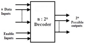
A binary decoder is a combinational logic circuit in digital electronics that converts binary information from n coded inputs into a maximum of 2n unique outputs. Binary decoders are widely used in various applications such as instruction decoding, data multiplexing and demultiplexing, seven-segment displays, and memory address decoding.
Regardless of its type or size, a decoder is an electronic circuit that uses multiple input and output signals to convert each unique combination of input states into a specific output combination. Some decoders include one or more enable inputs, which control the active state of the circuit. When the enable input is set to 0 (disabled), all decoder outputs remain inactive.
2-to-4 Binary Decoder
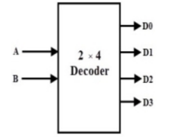
A 2-to-4 line binary decoder has three inputs — A0, A1, and E (Enable) — and four outputs — Y0, Y1, Y2, and Y3. When the enable input E is set to 1, one of the four outputs becomes high (logic 1) based on the binary input combination.
Block Diagram
Truth Table
| Enable (E) | A1 | A0 | Y3 | Y2 | Y1 | Y0 |
|---|---|---|---|---|---|---|
| 0 | x | x | 0 | 0 | 0 | 0 |
| 1 | 0 | 0 | 0 | 0 | 0 | 1 |
| 1 | 0 | 1 | 0 | 0 | 1 | 0 |
| 1 | 1 | 0 | 0 | 1 | 0 | 0 |
| 1 | 1 | 1 | 1 | 0 | 0 | 0 |
Logical Expressions
- Y3 = E · A1 · A0
- Y2 = E · A1 · A0′
- Y1 = E · A1′ · A0
- Y0 = E · A1′ · A0′
Logical Diagram
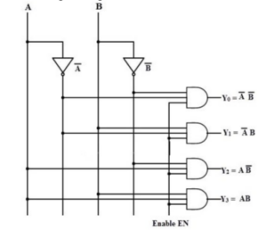
The logical diagram of a 2-to-4 decoder uses AND and NOT gates.
Each output is activated for a specific combination of binary inputs when the enable signal is high.
3-to-8 Binary Decoder
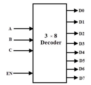
A 3-to-8 binary decoder converts three binary inputs (A, B, and C)
into eight unique outputs (Y0 to Y7).
It also includes an Enable (E) input that activates the decoder.
When E = 1, one of the eight outputs is high depending on the input combination.
Block Diagram
Truth Table
| E | A2 | A1 | A0 | Output (Y0–Y7) |
|---|---|---|---|---|
| 0 | x | x | x | All 0 |
| 1 | 0 | 0 | 0 | Y0 = 1 |
| 1 | 0 | 0 | 1 | Y1 = 1 |
| 1 | 0 | 1 | 0 | Y2 = 1 |
| 1 | 0 | 1 | 1 | Y3 = 1 |
| 1 | 1 | 0 | 0 | Y4 = 1 |
| 1 | 1 | 0 | 1 | Y5 = 1 |
| 1 | 1 | 1 | 0 | Y6 = 1 |
| 1 | 1 | 1 | 1 | Y7 = 1 |
Logical Expressions
- Y0 = A0′ · A1′ · A2′
- Y1 = A0 · A1′ · A2′
- Y2 = A0′ · A1 · A2′
- Y3 = A0 · A1 · A2′
- Y4 = A0′ · A1′ · A2
- Y5 = A0 · A1′ · A2
- Y6 = A0′ · A1 · A2
- Y7 = A0 · A1 · A2
Logical Expressions
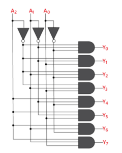
This decoder can be implemented using AND and NOT gates, where only one output line is high for each binary input combination when E is active.
Applications of Binary Decoder
- Used in analog-to-digital conversion as part of code conversion systems.
- Helps in data distribution and signal routing in digital circuits.
- Used to reduce decoding complexity in high-performance memory systems.
- Acts as an address decoder in CPUs for memory location identification.
- Converts instructions into CPU control signals in electronic circuits.
- Used in logical circuits and data transfer applications.
- Can be used to design adders and other basic digital circuits.
- Used by microprocessors to select I/O devices.
- Drives LED displays by decoding binary inputs into decimal numbers.
- Used in memory systems to select different memory banks.
- Activates outputs sequentially when driven by a pulsed counter input.
- Implements switching functions efficiently using fewer ICs.
Conclusion
A binary decoder plays a crucial role in digital systems by converting binary input codes into unique output combinations. It serves as a foundation for digital logic applications, including memory addressing, control systems, and data distribution. Understanding binary decoders is essential for anyone studying or working with digital electronics.