

Introduction
A Binary Weighted Digital-to-Analog Converter (DAC) is a circuit that converts digital binary data into a proportional analog output voltage. It consists of an operational amplifier configured as an inverting summing amplifier and a network of binary-weighted resistors. Each resistor corresponds to a specific binary bit, ranging from the Least Significant Bit (LSB) to the Most Significant Bit (MSB). Most real-world signals, such as audio, video, and sensor outputs, are analog in nature. However, digital systems process information in binary form.
Therefore, Digital-to-Analog Converters (DACs) are used to convert digital data back into analog signals for practical applications.


:contentReference[oaicite:0]{index=0}

What is a DAC?
A Digital-to-Analog Converter (DAC) is an electronic circuit that accepts digital data as input and produces an analog signal as output. The output voltage generated by the DAC is proportional to the binary code applied at its input.
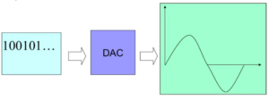

This analog output can then be used to drive various electronic devices and circuits.
:contentReference[oaicite:1]{index=1}
For example, in an audio system, the DAC converts digital audio data into a continuous analog waveform.
This analog signal is then amplified and reproduced through speakers.
:contentReference[oaicite:2]{index=2}
Binary Weighted Resistor DAC
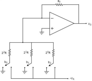
A Binary Weighted DAC uses resistors with values weighted according to binary progression. These resistors are connected to an inverting summing amplifier. Each input bit controls a switch that connects the corresponding resistor either to a reference voltage (VR) or to ground. The output voltage is obtained by summing the weighted contributions of all input bits.

The analog output is approximately proportional to the applied binary input.
:contentReference[oaicite:3]{index=3}
Working Principle
Consider a 3-bit Binary Weighted DAC with input bits:
- b2 – Most Significant Bit (MSB)
- b1 – Middle Bit
- b0 – Least Significant Bit (LSB)
Each bit can have only two possible values:
- 0 (Logic LOW)
- 1 (Logic HIGH)
When an input bit is equal to 0, the corresponding switch is connected to ground. When the input bit is equal to 1, the switch is connected to the reference voltage (VR). :contentReference[oaicite:4]{index=4} The non-inverting terminal of the operational amplifier is grounded. According to the virtual ground concept, the inverting terminal also remains at approximately 0V. This allows the currents through the weighted resistors to be summed accurately at the inverting input. :contentReference[oaicite:5]{index=5}
Output Voltage Equation
For a 3-bit Binary Weighted DAC, the output voltage is determined by the weighted contribution of each input bit. The generalized equation for an N-bit Binary Weighted DAC is:
:contentReference[oaicite:6]{index=6}
Where:
- Vout = Output Voltage
- VR = Reference Voltage
- bN-1 = Most Significant Bit (MSB)
- b0 = Least Significant Bit (LSB)
- N = Number of bits
Features of Binary Weighted DAC
- Uses an operational amplifier and weighted resistors.
- Provides analog output proportional to binary input.
- Simple circuit design.
- Fast conversion speed.
- Suitable for low-resolution applications.
Advantages of Binary Weighted DAC
- Simple circuit implementation.
- Low-cost DAC design.
- Requires only a resistor network and an operational amplifier.
- Provides fast digital-to-analog conversion.
- Easy to understand and design.
Because it uses a straightforward resistor network, the Binary Weighted DAC is one of the simplest DAC architectures. :contentReference[oaicite:7]{index=7}
Disadvantages of Binary Weighted DAC
- Maintaining accurate resistor ratios becomes difficult as the number of bits increases.
- Requires a wide range of resistor values.
- High precision resistors are needed for accurate conversion.
- Different resistor values carry different currents, requiring different power ratings.
- Conversion accuracy depends heavily on resistor tolerance and temperature stability.
- Large resistor values can introduce errors due to op-amp bias currents.
- Switch resistance may affect the accuracy of smaller resistor values.
For higher-bit DACs, obtaining precise and stable resistor values becomes difficult and expensive. :contentReference[oaicite:8]{index=8}
Applications of Binary Weighted DAC
- Audio Amplifiers
- Video Encoders
- Display Electronics
- Data Acquisition Systems
- Calibration Equipment
- Motor Control Systems
- Data Distribution Systems
- Digital Potentiometers
- Software-Defined Radio Systems
Binary Weighted DACs are widely used wherever digital data must be converted into an analog signal for processing or control purposes. :contentReference[oaicite:9]{index=9}
Conclusion
A Binary Weighted DAC is a simple and efficient digital-to-analog conversion circuit that uses weighted resistors and an operational amplifier to generate an analog output proportional to the digital input. Although it becomes less practical for high-resolution systems due to resistor accuracy requirements, it remains an important and widely studied DAC architecture in digital electronics and communication systems.