

Introduction
Conveyor systems are essential, highly efficient assets used in industrial settings to transport heavy loads, raw materials, and finished products throughout a facility. The primary goals of implementing automated conveyors are to lower workplace risks, maximize throughput, and save on labor costs. To maintain absolute control and operational safety, industrial conveyor systems are monitored by a suite of specialized safety devices, with the pull cord switch serving as the foundational emergency defense line.
What is a Pull Cord Switch?
A pull cord switch, also commonly referred to as a rope-operated emergency switch, is a safety control mechanism designed to instantly halt a belt conveyor system in the event of an accident or emergency. Because conveyor lines can span massive industrial footprints, multiple switches are deployed in series.

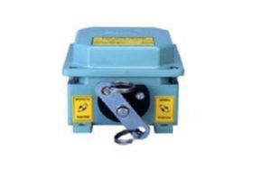
For maximum coverage, these safety switches are typically installed at intervals of every 15 to 20 meters along both sides of the belt conveyor assembly, providing workers with an immediate shutdown trigger from any position along the line.
Pull Cord Switch Construction and Key Components
Industrial pull cord switches are engineered to operate reliably under harsh environmental conditions. The primary structural components include:
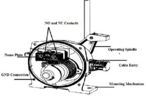
- Cast Aluminum Enclosure: A heavy-duty housing providing an IP65 grade of protection against heavy dust ingress and high-pressure water sprays.
- Name Plate: Affixed to the exterior shell, offering operators clear visibility regarding contact configuration types, serial numbers, and electrical ratings.
- Cable Entry Isolation: Features a robust rubber-grommet enclosure that seals the electrical cable entry point from moisture and particulates.
- Operating Spindle: Equipped with rugged steel rings designed to securely clamp and hold the structural pull wire or rope.
- Electrical Terminals: Contains heavy-duty contact blocks arranged in standard configurations (typically 2NO + 2NC) to interface seamlessly with industrial control logic.
- Manual Reset Button: Ensures that once the switch is pulled and tripped, the system remains locked out and cannot restart until an operator inspects the line and manually resets the lever.
Working Principle
The internal mechanism of a mechanical pull cord switch is exceptionally reliable. It consists of a high-tension internal spring, a precise cam assembly, and an electrical switch contact block. The switch can be configured for single-side pulling or dual-side operation.
A continuous PVC-coated steel wire rope is tensioned tightly along the length of the conveyor and anchored directly to the switch spindle. Under normal operating conditions, the tension from the spring counterbalances the rope, keeping the electrical contacts in their default state (Normally Closed contacts remain closed, keeping the conveyor running).
When an emergency occurs—such as an operator getting caught or noticing a mechanical failure—pulling the rope from any point along the line applies direct force to the spindle. This tension overcomes the internal spring mechanism, instantly shifting the internal cam to break the Normally Closed (NC) electrical paths and shut down the conveyor drive motor. The switch locks mechanically into this tripped state until it is manually reset at the physical switch box.
Technical Specifications
Standard industrial pull cord switches conform to the following baseline parameters to ensure reliable safety performance:
- Rated Operating Voltage: Optimized for standard industrial grid supplies at 230V AC (50Hz).
- Current Rating: Capable of handling active control line current loads up to 6 Amps.
- Housing Material: Crafted from corrosion-resistant, high-grade Cast Aluminum.
- Contact Configuration: Standard 2NO (Normally Open) + 2NC (Normally Closed) contact block matrix.
- Ingress Protection Grade: Rated at IP65 for robust dustproof and waterproof functionality.
- Rope Span Capacity: Capable of supporting continuous spans of tensioned safety wire rope up to 110 meters.
Types of Safety Switches Used in Conveyor Systems
While the standard pull cord switch protects personnel, several other auxiliary safety switches work alongside it to protect the mechanical health of the conveyor:
1. Belt-Sway Switch (Misalignment Switch)
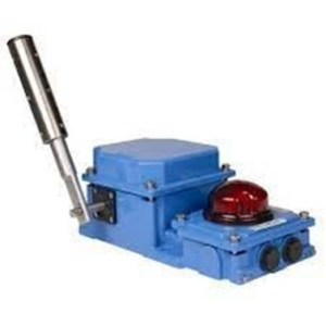
Installed in pairs on opposite edges of the conveyor belt, this switch features a heavy-duty roller lever. If the conveyor belt drifts off its tracking center due to uneven loading or wear, the belt edge pushes the roller. The switch then triggers an alarm or shuts down the system before the belt sustains severe edge damage.
2. Zero-Speed Switch
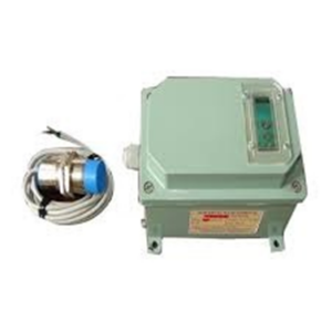
Designed to continuously track conveyor velocity using a non-contact sensor pulse and a dedicated control module. If the belt begins slipping on the drive pulley or drops below a preconfigured speed threshold due to mechanical overload, the switch flags a slow-speed signal and shuts down the system to prevent friction fires.
3. Heavy-Duty Limit Switch
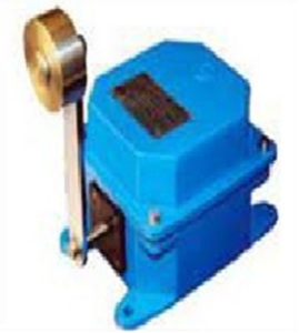
Housed inside robust, waterproof casings, these position sensors feature various roller handles. They are heavily utilized across industrial bulk handling applications, EOT overhead cranes, hoists, elevators, and transfer cars to monitor structural travel limits and prevent mechanical over-travel crashes.
4. Material Flow Switch
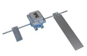
Consists of a movable paddle and a counterweight assembly suspended directly above or inside the material stream. If the product supply dries up or a chute blocks, interrupting the continuous material stream, the paddle moves, instantly generating a control system alarm to alert operators.
5. Damaged Belt Detector
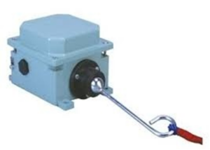
Positioned immediately beneath the conveyor belt, these low-maintenance, high-sensitivity detectors use flexible tear-wires or proximity fingers. If a sharp piece of scrap metal or rock punctures and rips the belt, the dangling flap hits the detector, triggering an immediate shutdown to prevent a catastrophic full-length belt tear.
Wiring Configuration and Control Loop Integration
To implement comprehensive safety coverage, pull cord switches are typically wired in a parallel loop configuration back to an industrial Programmable Logic Controller (PLC) or a dedicated safety relay matrix using heavy-duty two-core control cables.
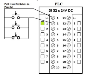
When wired in parallel to a central control safety monitor, triggering any single pull cord switch along the entire length of the production line completes or breaks the overarching safety loop. The system instantly drops out the main conveyor drive contactor, killing power to the belt assembly. The system remains safely locked out, refusing all startup commands until the exact tripped switch location is inspected and manually reset by field personnel.
Advantages
Exceptional mechanical reliability, robust long-life design tailored for severe outdoor weather, absolute emergency operator protection from any point along the line, integrated manual lockout verification, and available optional high-visibility LED trip indicators.
Disadvantages
Physically heavier and requires greater initial mounting space than standard proximity limit switches; higher initial hardware costs due to heavy cast-metal structures; and requires regular line checks to verify that environmental debris has not altered the physical tension of the wire rope.
Common Applications
Pull cord switches are mandatory emergency safety devices implemented across bulk material handling and packaging infrastructure. They are extensively deployed along cross-country belt conveyors operating in heavy industries such as coal mining facilities, thermal power plants, iron and steel mills, and cement production yards. Additionally, they are heavily relied upon to manage worker safety throughout high-speed food and beverage processing lines, automated packaging plants, and sorting warehouses.