

Introduction
Modern infrastructure—including hospitals, data centers, industrial manufacturing lines, and commercial buildings—relies heavily on a constant supply of electricity. To maintain operations during a main utility grid failure, these facilities utilize emergency power supplies like backup diesel generators or secondary utility feeds. A transfer switch serves as the critical safety device that shifts the electrical load between these two separate power sources safely and quickly.
What is a Transfer Switch?
A transfer switch is an electrical control mechanism designed to redirect load circuits between a primary power source (such as the main utility grid) and a secondary backup source (such as a generator). Its primary function is to prevent backfeeding—a highly dangerous situation where electricity flows backward from a home or building generator into the public power lines, risking the lives of utility repair workers.

By keeping both power sources completely isolated from each other, the transfer switch protects the facility’s internal electrical system, standardizes the transition process, and prevents generator damage. Industrial installations frequently feature automated hardware to handle high-amperage current switches seamlessly.
How Does a Transfer Switch Work?
The core operating principle of a transfer switch centers on monitoring the electrical load, supply voltage, and frequency levels. The system manages power routing through a sequential process:
- Outage and Drop Detection: The transfer switch actively monitors incoming voltage from the main utility line. When a power failure or severe brownout occurs, the voltage across the load circuit drops to zero.
- Inrush Current Management: When high-power equipment like industrial motors, furnace blowers, or large compressors attempt to restart after a power drop, they demand a massive surge of starting power known as inrush current. The transfer switch uses dedicated internal relay circuitry to buffer and manage this surge, preventing severe voltage drops or circuit damage.
- Load Isolation: Before connecting the backup power supply, the switch opens the contacts connecting to the main utility grid. This configuration acts as a physical air gap to ensure the secondary power source never contacts the primary line.
- Load Transfer: Once the backup generator stabilizes its voltage and frequency output, the internal relays or mechanical contacts close, routing steady emergency power directly to the facility’s distribution panel.
Types of Transfer Switches
Transfer switches generally fall into two main categories depending on how the switching mechanism is controlled:
1. Manual Transfer Switches
A manual transfer switch requires human intervention to change the power sources. When a blackout occurs, an operator must physically flip a heavy-duty mechanical lever on the switch box to disconnect the utility line and connect the generator lines.
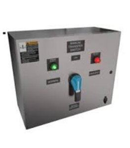
While manual switches are mechanically simpler and much less expensive, they are prohibited in safety-critical applications (such as hospital operating rooms or active data servers) where immediate, unattended power switching is mandatory.
2. Automatic Transfer Switches (ATS)
An Automatic Transfer Switch (ATS) operates as an intelligent, self-directed power relay system. The integrated microcontrollers constantly track utility grid health. The moment the main power goes down, the ATS commands the backup generator to start up, waits for the generator’s output to stabilize, and switches the electrical load automatically.
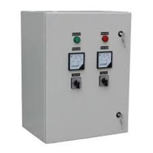
Once the primary utility grid is fully restored and verified stable, the ATS seamlessly transfers the load back to the grid and shuts down the generator without human interaction.
Basic Operational Sequence
The typical operational workflow follows a strict sequential cycle to protect downstream hardware:
- The normal utility power source fails or drops below an acceptable voltage threshold.
- The transfer switch logic controller sends a start command to the emergency generator.
- The generator engine cranks, stabilizes its RPMs, and outputs continuous power within fixed voltage and frequency limitations.
- The transfer switch safely shifts the electrical load from the normal source to the emergency source.
- When the standard utility grid power is fully restored, the switch automatically senses the steady voltage and shifts the facility load back to the primary line.
Advantages and Disadvantages
Advantages
- Continuous Automation: Models equipped with ATS functionality ensure minimal operational downtime during unexpected blackouts.
- Improved Safety: Eliminates backfeeding, mitigating the risk of electrical fires, equipment damage, or utility grid electrocution.
- Built-in Circuit Protection: Features intentional internal time delays that protect delicate electronics from initial grid voltage fluctuations.
Disadvantages
- Higher Capital Expense: Automatic models carry significantly higher upfront equipment and installation costs than manual switches.
- Maintenance Overhead: Requires regular testing, contact inspection, and control firmware updates to prevent mechanical failure.
- False Tripping: Highly sensitive diagnostic sensors can occasionally react to minor, temporary line noise or brief utility fluctuations, initiating unnecessary generator start cycles.
Common Applications
Transfer switches are deployed across a vast array of electrical distribution layouts:
- Residential Power Schemes: Paired with low-power portable or standby generators to maintain home HVAC systems, lighting, and refrigeration.
- Critical Care Facilities: Standardized across hospitals, eldercare facilities, and emergency command centers to maintain life-support gear.
- Complex Switching Arrangements: Extensively utilized in advanced industrial engineering configurations, including Utility-to-Utility, Generator-to-Generator, and multi-source emergency power topologies.