• Home
  • About Us
  • Contact Us
Semiconductor for You
  • Home
  • Semiconductor News
  • Technology
    • Automotive
    • Consumer Electronics
    • IoT
    • Lighting
    • Power Management
    • Wireless
    • Personal Electronics
    • Hardware & Software
    • Research
    • Medical Electronics
    • Embedded Design
    • Aerospace & Defence
    • Artificial Intelligence
  • DIY Projects
  • Market
  • Industries
    • Renesas Electronics
  • Knowledge Base
  • Events
  • Tools
    • Resistor Color Code Calculator
No Result
View All Result
Semiconductor for You
No Result
View All Result
Home Knowledge Base

Common Gate Amplifier Circuit and Its Applications

Bhushan Chaudhary by Bhushan Chaudhary
September 20, 2022
in Knowledge Base
0
ADVERTISEMENT

What is Common Gate Amplifier?

  • A common-gate amplifier is one of three basic single-stage field-effect transistor (FET) amplifier topologies used in electronics, typically as a current buffer or voltage amplifier. In this circuit, the transistor’s source terminal serves as the input, the drain serves as the output, and the gate is connected to ground, or “common,” hence the name. The common-base amplifier is an analogous bipolar junction transistor circuit.
  • A CG stage is a current buffer with a current gain of about one, a low input resistance, and a high output resistance. It takes a current from the input, which may have a low Norton equivalent resistance, and replicates it at the output, which is a good current source due to the high output resistance.
  • The CG amplifier shown below senses the input signal at the source terminal and produces the output at the drain terminal. The gate terminal is connected to VB, or dc potential, which ensures that the proper operating conditions are maintained.
Common Gate Amplifier

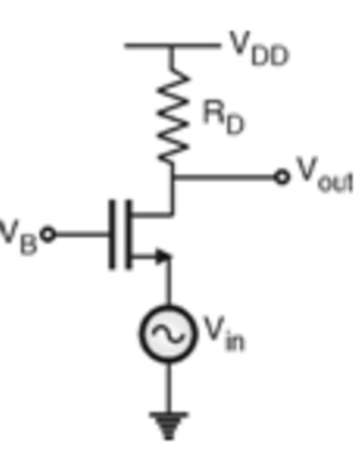
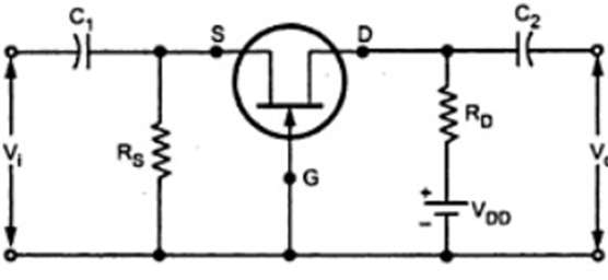
FET Common Gate Amplifier Circuit

  • In this circuit, input is connected between the source and the gate, and output is connected between the drain and the gate.
Circuit Diagram of Common Gate Amplifier
  • The gate potential is constant in the CG configuration. As a result, increasing the input voltage Vi in the positive direction raises the negative gate source voltage. ID decreases, decreases, decreases the drop IDRD. Because VD= VDD-IDRD, decreasing ID results in an increase in output voltage.
Small Signal Equivalent Circuit of the CG Amplifier
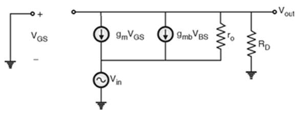
  • By analyzing the small signal equivalent circuit we can get Input impedance, output impedance and voltage gain,
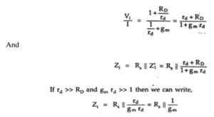
  • 1. Input impedance (Zi)

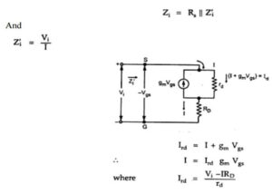
  • After substituting and simplification,

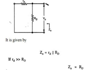
2. Output Impedance (Zo)

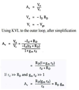
3. Voltage gain (Av)

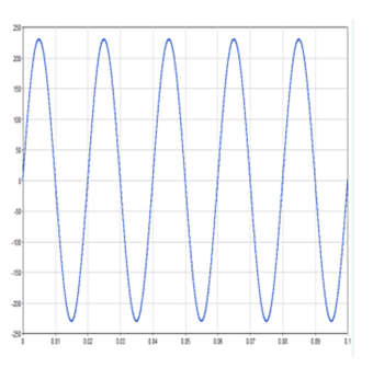
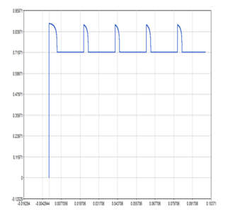
Waveforms of Common Gate Amplifier Circuit

Input Voltage
Output Voltage

FET Common Gate Applications

  • Because it often provides very few advantages over other configurations, the FET common gate circuit is not as widely used as other FET configurations. There are some instances where it is extremely beneficial.
  • RF amplifiers: The common gate or grounded gate circuit configuration is used for VHF and UHF RF amplifiers because the low input impedance allows for accurate matching to the feeder impedance, which is typically 50 or 75. The configuration also improves stability, which is an important consideration. Because the gate is grounded, it provides isolation between the input and output, greatly reducing the possibility of feedback.
  • The common Gate amplifier is used as a Current Buffer Amplifier; it has a low input resistance and a high output resistance.
  • Microphone amplifiers: The common gate circuit configuration is used in amplifiers with low input impedance levels. Moving-coil microphone preamplifiers are one application; these microphones have extremely low impedance levels.
Content Protection by DMCA.com
Bhushan Chaudhary

Bhushan Chaudhary

Browse by Category

  • Aerospace and Defence
  • Articles
  • Automotive
  • Consumer-Electronics
  • Hardware & Software
  • Interview
  • IoT
  • Knowledge Base
  • Lighting
  • Market
  • personal-electronics
  • Power Management
  • Research
  • Semiconductor Events
  • Semiconductor News
  • Technology
  • Wireless
Semiconductor for You

Semiconductor For You is a resource hub for electronics engineers and industrialist. With its blend of
technology features, news and new product information, Semiconductor For You keeps designers and
managers up to date with the fastest moving industry in the world.

Follow Us

Browse by Category

  • Aerospace and Defence
  • Articles
  • Automotive
  • Consumer-Electronics
  • Hardware & Software
  • Interview
  • IoT
  • Knowledge Base
  • Lighting
  • Market
  • personal-electronics
  • Power Management
  • Research
  • Semiconductor Events
  • Semiconductor News
  • Technology
  • Wireless

Recent News

TDK expands thin-film power inductors for automotive applications to higher currents

TDK expands thin-film power inductors for automotive applications to higher currents

July 2, 2025
Renesas Strengthens Power Leadership with New GaN FETs for High-Density Power Conversion in AI Data Centers, Industrial and Charging Systems

Renesas Strengthens Power Leadership with New GaN FETs for High-Density Power Conversion in AI Data Centers, Industrial and Charging Systems

July 2, 2025
  • About
  • Advertise
  • Privacy & Policy
  • Contact

© 2022 Semiconductor For You

No Result
View All Result
  • Home
  • Semiconductor News
  • Technology
    • IoT
    • Wireless
    • Power Management
    • Automotive
    • Hardware & Software
  • Market
  • Knowledge Base
  • Tools
    • Resistor Color Code Calculator

© 2022 Semiconductor For You