What is Common Source Amplifier?
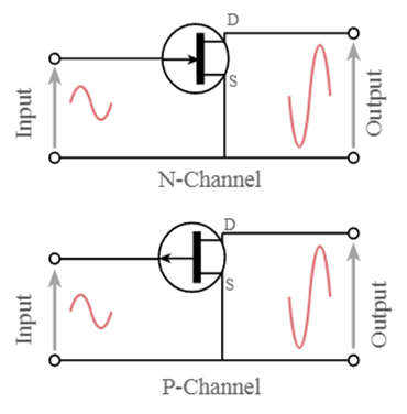
- A common-source amplifier is one of three basic single-stage field-effect transistor (FET) amplifier topologies used as a voltage or transconductance amplifier in electronics. The simplest way to determine whether a FET is a common source, common drain, or common gate is to look at where the signal enters and exits. The remaining terminal is referred to as “common.” The signal enters the gate and exits the drain in this example. The source is the only remaining terminal.
- This is a FET circuit with a common source. The analogous bipolar junction transistor circuit can be viewed as a voltage amplifier or a transconductance amplifier. (See amplifier classification.) The input voltage is seen as modulating the current going to the load in a transconductance amplifier. The input voltage modulates the current flowing through the FET as a voltage amplifier, changing the voltage across the output resistance according to Ohm’s law.
FET Common Source Amplifier Circuit
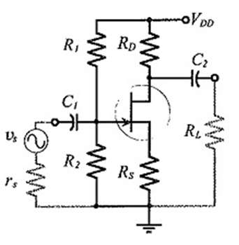
- The common source amplifier circuit diagram with N-channel FET coupling and biasing capability is shown below. This circuit will be similar to a Bipolar Junction transistor’s common-emitter follower. The polarity of the input voltage will be reversed if we use a P-channel FET.
- Among other JFET configurations, the common source amplifier configuration is widely used because it can provide both high voltage gain and a large input impedance.
- There are three terminals on the common source FET amplifier. They are as follows: source, gate, and drain.
Source:

ADVERTISEMENT
- This terminal receives the majority of the carriers required by the device. Current enters the channel via a source terminal, which is denoted by IS.
Drain:
- This terminal is where the majority of the carriers in the channel exit. That is exhausting. As a result, conventional current enters the channel, denoted by ID.
Gate:
- This terminal is always in charge of the channel’s conductivity. As a result, the flow of current in the output is controlled by a voltage level across the gate.
- This amplifier can provide medium input Impedance, medium output impedance, medium current gain, medium voltage gain, and reverse output concerning input which means the output signal will be in 180 degrees phase change. From these characteristics, we can conclude that this amplifier can give high-level performance over other amplifier circuits like a common drain (source follower) and common gate. Hence it is most widely used than other amplifier circuits.
Common Source Amplifier Working
- This amplifier can function as a transconductance amplifier or a voltage amplifier. If the amplifier is acting as a transconductance amplifier, the input signals are amplified and modulate the current flowing to the load. If the amplifier is acting as a voltage amplifier, the input signal is amplified and modulated, changing the voltage across the load resistor according to Ohm’s law.
- The above circuit diagram explains how a common source amplifier works. Its operation is similar to that of a common-emitter follower in a BJT circuit.
- When the input signal is routed through the capacitor C1 to the gate terminal. This capacitor is used to determine whether the gate terminal is affected by any DC voltage from the previous stage. The potential is held by the resistor R2 of around 1Mega ohms located between the gate and the ground. The voltage is generated across the resistor R2, which keeps the source above ground. The bypass capacitor C2 adds gain to the alternating current signal.
- The amplified output voltage is obtained by crossing the resistor R3 at the load at the circuit’s drain terminal. The capacitor C3 couples the amplified output voltage to the AC signal of the next stage by blocking or eliminating the DC components. This amplifier’s amplified output signal is 180 degrees out of phase concerning the input signal and produces a high power gain.
- The operation of the P-channel common source amplifier FET is similar to that of the N-channel common source amplifier FET, with the exception that the voltage polarities are reversed. There will be no current flowing between the gate and the source in the reverse-biased state. As a result, the gate current is zero. The gate voltage (DC) is then given as.
Vg = Ig x Rg - The DC voltage at the source is given by,
Vs = Id x Rs - Then the gate to source voltage is given by,Vgs = Vg – Vs = 0- Id x RsSince Ig = 0
Vgs = – Id x Rs
Where,
Vgs = gate-source voltage
Vg = gate voltage
Rs = resistor at the source
Rg = resistor at Gate
Ig = gate current - The flow of DC components in the drain current can cause the resistor Rs to self-bias and provide feedback from the output to the input.
Applications of FET Common Source Amplifier Circuit
- Used in sensor signal amplification.
- RF signal amplification with low noise.
- Used in communication systems such as television and FM receivers.
- In op-amps, they are used as voltage-controlled devices.
- Cascade amplifiers and RF amplifier circuits are examples of their applications.