- Flex sensor typically come in two sizes. One is 2.2 inches long and the other is 4.5 inches long. Despite the differences in size, the basic function remains the same. They are also divided according to resistance.
- There are three levels of resistance: LOW, MEDIUM, and HIGH. Depending on the situation, select the appropriate type.
- A flex sensor is a type of sensor that measures the amount of defection or bending. This sensor can be designed using materials such as plastic and carbon.
- The carbon surface is arranged on a plastic strip, and when this strip is turned away, the sensor’s resistance changes.
- As a result, it is also known as a bend sensor. Because its varying resistance is directly proportional to the number of turns, it can also be used as a goniometer.
- The appropriate size can be chosen based on the need. This article provides an overview of the 2.2-inch flex-sensor.
- This type of sensor is used in a variety of applications, including computer interface, rehabilitation, servo motor control, security systems, music interface, intensity control, and anywhere the consumer needs to change the resistance while bending.
Pin Configuration
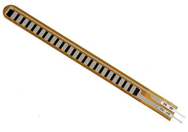
- The flex sensor’s pin configuration is shown below. It is a two-terminal device with the terminals p1 and p2. This sensor does not have any polarised terminals, such as a diode or a capacitor, so there are no positive and negative terminals.
- This sensor’s required voltage ranges from 3.3V to -5V DC, which can be obtained through any type of interfacing.
- Pin P1: This pin is typically connected to the power source’s +ve terminal.
- Pin P2: This pin is typically connected to the power source’s GND pin.
Where To Use Flex Sensor?
- For understanding the use of FLEX SENSOR considers.
- Case 1: When you want to see if the surface of a device or thing is leveled. Assume you want a device that can detect whether a window or door is open or closed. A Flex sensor could be used at the time.
- The sensor could be attached to the door’s edge, and when the door opens, the Flex sensor flexes.
- When the sensor is flexed, its parameters change, which could be programmed to generate an alert.
- Case 2: You want to measure the change in FLEX, BENT, or ANGLE of any instrument or device.
- The internal resistance of the FLEX SENSOR varies almost linearly with its flex angle. So, by attaching the sensor to the instrument, we can obtain the flex angle in electrical resistance parameters.
Working Principle
- As previously stated, a FLEX SENSOR is essentially a VARIABLE RESISTOR whose terminal resistance increases as the sensor is bent.
- As a result, the sensor resistance increases as the surface linearity increases. As a result, it is commonly used to detect changes in linearity.
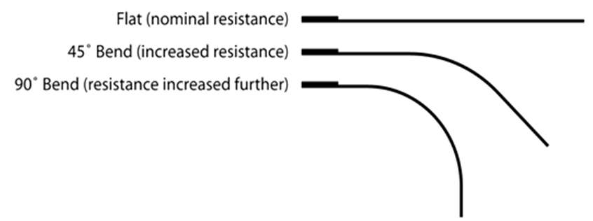
- When the surface of the FLEX SENSOR is completely linear, as shown in the above figure, it will have its nominal resistance. When it is bent at a 45o angle, the FLEX SENSOR resistance doubles.
- When the bend is 90o, the resistance can reach four times the nominal resistance. As a result, the resistance across the terminals increases linearly with the bent angle. In some ways, the FLEX sensor converts the flex angle to the RESISTANCE parameter.
- We convert the RESISTANCE parameter to the VOLTAGE parameter for convenience. We will use a VOLTAGE DIVIDER circuit for this. The circuit diagram for a typical VOLTAGE DIVIDER is shown below.
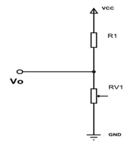
- We have two resistances in this resistive network. The first is constant resistance (R1), and the second is variable resistance (R2) (RV1). Vo denotes the voltage at the midpoint of the VOLTAGE DIVIDER circuit, as well as the output voltage.
- Vo is the voltage across the variable resistance as well (RV1). As a result, as the resistance value of RV1 changes, so does the output voltage Vo.
- As a result, the resistance will change as the voltage changes with the VOLTAGE DIVIDER circuit.
- FLEX SENSOR will be used in place of the variable resistance (RV1). The circuit will look like this.
- As shown in the figure, R1 is a constant resistance, and FLEX SENSOR is a variable resistance. Vo denotes the output voltage as well as the voltage across the FLEX SENSOR.
- In this case, Vo = VCC (Rx/(R1+Rx)).
- Resistance to Rx – FLEX SENSOR.
- The terminal resistance now increases when the FLEX SENSOR is bent. This increase is also visible in the VOLTAGE DIVIDER circuit. As the drop across the FLEX SENSOR rises, so does Vo. As a result, as the bend of the FLEX sensor increases, so does the voltage. With that, we have the VOLTAGE parameter, which represents the flex.
- We can take this VOLTAGE parameter and feed it to an ADC to get a digital value that we can use.
Applications of Flex Sensor
- Robotics
- Gaming (Virtual Motion)
- Medical Devices
- Computer Peripherals
- Musical Instruments
- Physical Therapy