Introduction
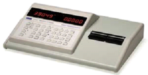
An LCR meter, also known as an LCR bridge, is a test instrument used to measure the inductance (L), capacitance (C), and resistance (R) of electronic components. LCR meters are specialized test instruments commonly used for inspection to ensure that incoming components meet specifications. They are also widely used in development laboratories to evaluate the actual performance of components.
The name LCR meter is derived from the parameters it measures: inductance (L), capacitance (C), and resistance (R). Some LCR meters use a bridge circuit as the basis of their operation, which is why they are often called LCR bridges. Simple LCR meters display impedance and calculate inductance or capacitance from it. More advanced LCR bridges can directly measure inductance, capacitance, equivalent series resistance (ESR), dissipation factor (tan δ) of capacitors, and the quality factor (Q) of inductors.
LCR Meter Basics
LCR meters use different measurement techniques depending on the accuracy required and the frequency range of operation. The two most common methods are the bridge method and the current-voltage (I-V) measurement method.
Bridge Method
The bridge method is based on the well-known Wheatstone bridge principle. The aim is to balance the bridge so that no current flows through the detector. At balance, the value of the unknown component can be calculated from the known bridge elements.
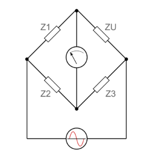
basic bridge based LCR meter circuit
In this method, the device under test (DUT) is placed in one arm of the bridge circuit. The values of the other bridge components are adjusted until balance is achieved. Bridge-based LCR meters are typically used for low-frequency measurements, usually up to about 100 kHz. Instruments that use this technique are commonly referred to as LCR bridges.
Current-Voltage (I-V) Measurement Method
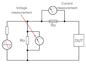
The current-voltage measurement method is commonly used for higher-frequency applications. It provides high accuracy over a wide frequency range and is suitable for modern electronic components. This technique, also known as the RF I-V method, measures both the voltage across and the current through the device under test. The measurement circuit is impedance matched to ensure accuracy at high frequencies.
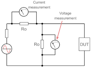
IV LCR Measurement for low impedance circuits
For very high-frequency and high-precision measurements, a coaxial test port may be used. There are two basic I-V measurement configurations: one for low-impedance measurements and another for high-impedance measurements.
IV LCR Measurement for high impedance circuits
Using the measured voltage, current, and their phase difference, the impedance of the DUT can be calculated. A phase-sensitive detector separates the resistance and reactance components, allowing inductance or capacitance to be displayed directly.
Transformers are often used in I-V measurement circuits to provide isolation from ground and improve measurement accuracy. However, transformers may limit the lower frequency range of the instrument.
LCR Bridge Measurement Guidelines
Effect of Lead Length
Lead length can significantly affect measurements at frequencies above 1 MHz. A rough estimate of lead inductance is approximately 10 nH per centimetre. To minimise errors, test leads should be kept as short as possible.
Measure at Operating Frequency
Measurements should be performed at a frequency close to the component’s actual operating frequency. This reduces errors caused by frequency-dependent behaviour, such as changes in inductor core properties.
Adjust Test Amplitude
Component values may vary with signal amplitude. This is particularly important for inductors with ferrite cores, where losses and inductance can change with excitation level. Therefore, test amplitude should match real operating conditions as closely as possible.
Discharge Capacitors Before Measurement
Some capacitors can retain a residual charge for a long time. Always discharge capacitors before measurement to avoid incorrect readings and potential damage to the instrument.
Applications of LCR Meters
LCR meters and bridges are extremely useful test instruments. While they are no longer widely used for incoming component inspection in mass production, they are still commonly used in laboratories and workshops.
- Measurement of inductance, capacitance, and resistance
- Testing component quality using Q factor and dissipation factor
- Evaluating equivalent series resistance (ESR) of capacitors
- Component characterisation in research and development
- Fault finding and troubleshooting in electronic circuits
Due to their versatility and accuracy, LCR meters remain essential tools for engineers, technicians, and researchers working with electronic components.