- It is a type of positive-linear-voltage regulator that was invented in 1970 by Robert C. Dobkin and Robert J. Widlar while working at National Semiconductor. It is a three-terminal adjustable voltage regulator that is simple to use because it only requires two external resistors to set the output voltage in the LM317 voltage regulator circuit. It is primarily employed for local and on-card regulation. If we connect a fixed resistor between the LM317 regulator’s output and adjustment, we can use the LM317 circuit as a precision current regulator.
LM317 Voltage Regulator Circuit
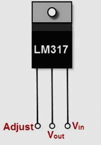
- The input pin, output pin, and adjustment pin are the three terminals. The LM317 circuit diagram shown below is a typical configuration of the LM317 voltage regulator circuit diagram, which includes the decoupling capacitors. This LM317 circuit can provide a variable DC power supply with an output of 1A and an adjustment range of up to 30V. A low-side and high-side resistor are connected in series to form a resistive voltage divider, which is a passive linear circuit used to produce an output voltage that is a fraction of its input voltage.
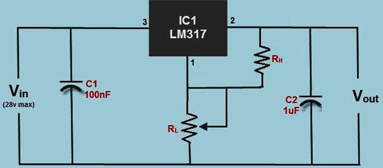
- Decoupling capacitors are used to decouple or prevent unwanted coupling between two parts of an electrical circuit. To avoid the effect of noise caused by some circuit elements on the remaining circuit elements, decoupling capacitors are used in the circuit to address input noise and output transients. A heat sink is used in conjunction with the circuit to prevent the components from becoming overheated as a result of increased power dissipation.
Working of Voltage Regulator LM317 Circuit
- Because the LM317 regulator can provide excess output current, it is conceptually considered an operational amplifier. The adjustment pin is the amplifier’s inverting input, and an internal bandgap reference voltage is used to set the non-inverting input to produce a stable reference voltage of 1.25V.
- A resistive voltage divider between the output and ground can be used to continuously adjust the output pin voltage to a fixed amount, converting the operational amplifier to a non-inverting amplifier.
- A bandgap reference voltage is used to produce constant output voltage regardless of supply power changes. It is also known as a temperature-independent reference voltage, and it is commonly used in integrated circuits.
- The output voltage of the LM317 voltage regulator circuit (ideally).
- Vout = (1+ (RL/RH)) * Vref
- Because some quiescent current flows from the device’s adjustment pin, an error term is added.
- Vout = (1+(RL/RH)) * Vref + IQR
- The LM317 voltage regulator circuit diagram is designed to achieve a more stable output by keeping the quiescent current less than or equal to 100 micro Ampere. As a result, the error can be ignored in all practical cases.
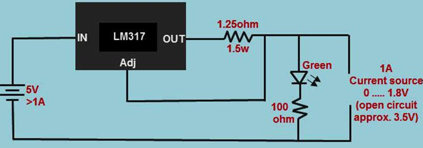
- If we substitute the load for the low-side resistor of the divider in the LM317 voltage regulator circuit diagram, the resulting configuration of the LM317 regulator will regulate the current to a load. As a result, this LM317 circuit can be referred to as the LM317 Current Regulator Circuit.
- The output current is the voltage drop of the reference voltage across the resistance RH and is given as Iout = Vref/RH in the ideal case.
- Taking the quiescent current into account, the output current is given as Iout = (Vref/RH) + IQ.
- The LM317 and LM337 linear voltage regulators are frequently used in DC-DC converter applications. Linear regulators are designed to draw as much current as they supply. The power generated by multiplying this current by the voltage difference between the input and output is dissipated and wasted as heat.
- As a result, heat must be considered for significant design, which leads to inefficiency. When the voltage difference increases, so do the power wasted, and this dissipated waste power can sometimes exceed the supplied power.
- Even though this is insignificant, we must accept this trade-off because linear voltage regulators with a few additional components are a simple way to obtain stable voltage. Switching voltage regulators are an alternative to linear regulators because they are generally more efficient, but they require more components to design and thus take up more space.
Applications of LM317 Voltage Regulator
- Use all power supplies to electronic devices to regulate voltage and protect the device.
- To regulate the output of an alternator in an internal combustion engine.
- To regulate the output of an alternator in an internal combustion engine.