• Home
  • About Us
  • Contact Us
Semiconductor for You
"
  • Home
  • Semiconductor News
  • Technology
    • Automotive
    • Consumer Electronics
    • IoT
    • Lighting
    • Power Management
    • Wireless
    • Personal Electronics
    • Hardware & Software
    • Research
    • Medical Electronics
    • Embedded Design
    • Aerospace & Defence
    • Artificial Intelligence
  • DIY Projects
  • Market
  • Industries
    • Renesas Electronics
  • Knowledge Base
  • Events
  • Tools
    • Resistor Color Code Calculator
No Result
View All Result
Semiconductor for You
No Result
View All Result
Home Knowledge Base

MJE13005 NPN Transistor : Pin Configuration & Its Working

Bhushan Chaudhary by Bhushan Chaudhary
August 20, 2022
in Knowledge Base
0
ADVERTISEMENT
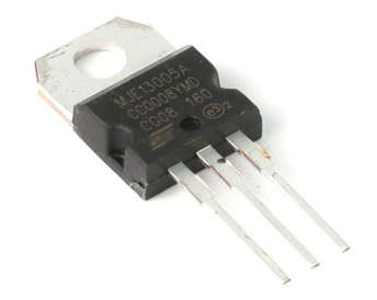
  • The MJE13005 is a high-speed, high-power NPN transistor that is used for amplification and switching.
  • This component is composed of three layers, one of which is p-doped and the other two of which are n-doped. Between these two n-doped layers is the p-doped layer.
Practical MJE13005 Transistor
  • The MJE13005 is a silicon-based semiconductor device. It is a current-controlled device with three terminals known as emitter, base, and collector, as opposed to MOSFETs, which are voltage-controlled devices with three terminals known as source, drain, and gate.
  • All of these terminals have varying levels of doping. In comparison to the other two terminals, the collector pin has a low doping concentration and the emitter pin has a high doping concentration. The collector pin is ten times more doped than the base pin. Furthermore, because the emitter current is the sum of the collector and base currents, the emitter side carries the entire current of the device.
  • Bipolar junction transistors are divided into two types: NPN transistors and PNP transistors.
  • In both of these transistors, electrons, and holes play critical roles in conductivity. However, in NPN transistors, holes are the majority carriers, whereas, in PNP transistors, holes are the minority carriers.
  • NPN transistors are preferred over PNP transistors for a variety of applications because electron mobility is greater than hole mobility.
  • • Because they sink ground to the output, NPN devices are sometimes referred to as “sinking devices.” PNP devices are sometimes referred to as “sourcing devices” because they supply positive power to the output.
  • This device’s DC gain ranges from 8 to 40, indicating the amount of current it can amplify.

Pin Configurations


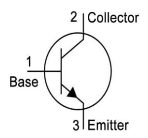
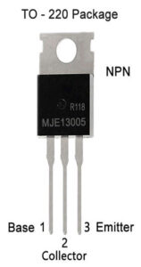
The pin diagram of the MJE13005 NPN Transistor is shown below.

  • Base – Controls the biasing of the transistor; used to turn the transistor ON or OFF.
  • Collector – Current enters the collector, which is normally connected to the load.
  • Emitter – Current drains through the emitter, which is normally connected to ground.

Features and Specifications

  • NPN Transistor with a High Voltage.
  • DC Current Gain (hFE) ranges from 8 to 40.
  • The constant collector current (IC) is 4A.
  • VCE (collector-emitter voltage) is 400 V.
  • The collector-base voltage (VCB) is set to 700V.
  • The emitter-base voltage (VBE) is 9 volts.
  • The base current is 2A. (max).
  • To-220 package is available.

Applications of MJE13005 NPN Transistor

  • They are particularly suited for 115 and 220V switch mode applications such as switching regulators, inverters, DC-DC converters, motor controls, solenoid/relay drivers, and deflection circuits.
  • Uninterruptible Power Supply.
  • Circuits such as power supplies and battery chargers.
  • In current electronic circuits.
  • Used in Astable & Bistable Multivibrators.
  • Used in the SMPS.
Content Protection by DMCA.com
Bhushan Chaudhary

Bhushan Chaudhary

Browse by Category

  • Aerospace and Defence
  • Articles
  • Automotive
  • Consumer-Electronics
  • Hardware & Software
  • Interview
  • IoT
  • Knowledge Base
  • Lighting
  • Market
  • personal-electronics
  • Power Management
  • Research
  • Semiconductor Events
  • Semiconductor News
  • Technology
  • Wireless
Semiconductor for You

Semiconductor For You is a resource hub for electronics engineers and industrialist. With its blend of
technology features, news and new product information, Semiconductor For You keeps designers and
managers up to date with the fastest moving industry in the world.

Follow Us

Browse by Category

  • Aerospace and Defence
  • Articles
  • Automotive
  • Consumer-Electronics
  • Hardware & Software
  • Interview
  • IoT
  • Knowledge Base
  • Lighting
  • Market
  • personal-electronics
  • Power Management
  • Research
  • Semiconductor Events
  • Semiconductor News
  • Technology
  • Wireless

Recent News

AI-Ready MCUs and the Road Ahead

AI-Ready MCUs and the Road Ahead

May 14, 2025
Renesas Collaborates with Indian Government to Empower Startups and Boost Semiconductor Innovation

Renesas Collaborates with Indian Government to Empower Startups and Boost Semiconductor Innovation

May 13, 2025
  • About
  • Advertise
  • Privacy & Policy
  • Contact

© 2022 Semiconductor For You

No Result
View All Result
  • Home
  • Semiconductor News
  • Technology
    • IoT
    • Wireless
    • Power Management
    • Automotive
    • Hardware & Software
  • Market
  • Knowledge Base
  • Tools
    • Resistor Color Code Calculator

© 2022 Semiconductor For You