Introduction
A Q meter is a testing instrument used for measuring the quality factor (Q) of electrical circuits at radio frequencies. Although modern impedance measuring devices have largely replaced it in professional laboratories, it remains popular among radio amateurs for educational and experimental purposes.
The Q meter measures the storage factor or quality factor of an electrical circuit, which indicates the relationship between stored and dissipated energy. The higher the Q value, the lower the energy loss within the circuit. The instrument helps evaluate the characteristics of coils and capacitors, especially in RF applications.
What Is the Quality Factor of a Coil?
The quality factor (Q) of a coil is defined as the ratio of its inductive reactance to its effective resistance:
Q = XL / R
where XL is the inductive reactance and R is the effective resistance of the coil.
Circuit Diagram
The Q meter operates on the principle of series resonance. When an AC series circuit reaches resonance, the voltage across the capacitor is equal to the applied voltage multiplied by the quality factor of the circuit. A voltmeter connected across the capacitor can be calibrated to read the Q value directly.
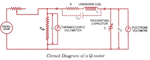
In a practical Q meter circuit, the oscillator is tuned to the desired frequency, and the tuning capacitor (C) is adjusted to its maximum value. The input voltage is kept constant, and the voltage across the capacitor (Vc) is measured and calibrated to directly indicate the Q value. The measured value represents the Q of the entire circuit rather than just the coil, with minor errors due to shunt resistance and distributed capacitance.
Corrections
- Correction of Shunt Resistance
- Correction of Distributed Capacitance
- Measurement of Self Capacitance – Knowing the values of f₀ and C, the inductance can be calculated.
- Measurement of Effective Resistance – The effective resistance can be computed using the appropriate circuit relations.
Working Principle
The Q meter works on the series resonant principle. Resonance occurs when the reactances of the capacitance and inductance are equal in magnitude but opposite in phase, allowing energy to oscillate between the electric and magnetic fields of the capacitor and inductor respectively. The instrument primarily depends on the capacitance, inductance, and resistance of the resonant circuit.
Factors That May Cause Error
1. Shunt Resistance (Rsh)
At high frequencies, the electronic voltmeter may experience losses due to the transit time effect. The shunt resistance Rsh adds extra resistance to the tank circuit. It affects the accuracy of the measured Q, as described below:
Qact = True Q | Qobs = Observed Q
To minimize error, Rsh should be kept as small as possible. A value between 0.02 and 0.04 introduces negligible error.
2. Distributed or Self Capacitance
The most significant source of error is the distributed (or stray) capacitance in the measuring circuit. This affects the actual Q and inductance of the coil. At the resonant frequency, the circuit impedance is purely resistive when the coil’s inductance and distributed capacitance balance each other. This property can be used to determine the distributed capacitance of the coil.
Method 1 – Graphical Method
One method of determining a coil’s distributed capacitance (Cs) is to plot a graph of 1/f² versus C (in picofarads). The oscillator frequency of the Q meter is varied, and the capacitance for each resonance point is recorded. The resulting straight line intersects the X-axis to give the value of Cs. The same formula can also be used to calculate the unknown inductance.
Method 2 – Dual Frequency Method
Another method involves taking two resonance measurements at different frequencies. The test coil is connected to the Q meter terminals, and the tuning capacitor is set to its maximum value. The circuit is first resonated at frequency f₁ with capacitor value C₁.
The oscillator frequency is then doubled (f₂ = 2f₁), and the capacitor is adjusted until resonance occurs at C₂. For resonance, the total capacitance of the circuit is:
(C₁ + Cs) for the first condition, and (C₂ + Cs) for the second condition.
Using these relations, the distributed capacitance Cs can be calculated accurately.
Applications
- Measures the quality factor (Q) of coils and circuits.
- Determines effective resistance, inductance, and capacitance.
- Measures bandwidth and resonant frequency of RF circuits.
- Used for evaluating component characteristics in laboratories.
- Helpful in educational and research experiments involving tuned circuits.
Conclusion
The Q meter remains a valuable tool for understanding and measuring the performance of RF coils and resonant circuits. Despite being replaced by modern instruments, it offers clear insights into parameters like quality factor, distributed capacitance, and resonance behavior, making it an excellent educational and analytical device.