
A rectifier diode allows the electrical current to flow in only one direction. It is mainly used for power supply operations. Rectifier diodes can handle the flow of higher currents than other regular diodes. These diodes are generally used to change alternating current (AC) into direct current (DC). The process is known as rectification since it “straightens” the direction of the current. If power is coming from the positive side of the external source to the anode of the diode it will allow the current to pass through it, but if we change the direction of the diode like current is coming from the positive side of the external source to the cathode of the diode it will not allow the current to pass through it.
V- I characteristics of the rectifier diode
Unbiased condition of the rectifier diode
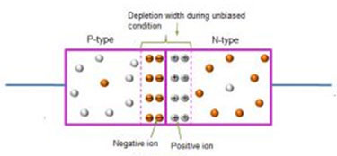
When there is no voltage is supplied to a rectifier diode then it is called an unbiased diode or zero biased diodes. N-side has a majority of electron carriers, and a very small number of holes, where the P- side has a majority of positively charged carriers holes and very a small number of numbers of electrons. The immobile in the n-type side near the junction edge. Similarly, the immobile ions in the p-type side near the junction edge. Hence, this accumulation of charges across the region forms the depletion region is a diode.
 Forward biased condition of the rectifier diode
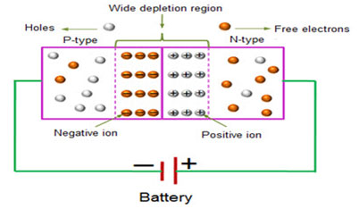
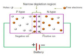
In a forward-biased condition, the device is connected i.e., P-type is connected to the positive terminal of the battery, and N-type is connected to the negative terminal of the battery, the diode is said to be in forwarding bias condition. Here P-type is having positive charges and it is connected to the positive terminal of the battery, if we have the same charges there is always repulsion. Positive charges are connected to the positive terminal it will repel holes away from P-type and they will move towards N-type. So as in the N-type region electrons get repelled and drift towards the junction and across the junction, and hole also coming towards the junction the depletion region width will get reduced because of the repulsion. So because of the narrow depletion region, it will be easier for the carrier to travel towards the next junction. So, the overall current due to majority carriers creates a current that current is known as Drift Current. Hence the diode will start conducting when it is forward biased.
Reverse biased diode
In a reverse-biased, the supply will be reversed. The positive terminal of the source is connected to the n-type end, and the negative terminal of the source is connected to the p-type end of the diode. Now when the positive terminal of the battery is connected to the N-type of material that has negative charges they will attract each other as they have opposite charges. The electrons will attract and they will drift toward the potential point not towards the junction, they will move away from the junction. Similarly in P-type material positively charged carrier holes will attract towards and moves away from the junction. As the holes and electrons are moving away from the junction this might leads to the depletion region wider. The width of the depletion region will increase in reverse biased. Due to the wider depletion region, the carriers from N-type cannot flow from N-type to P-type, and holes from P-type cannot drift from P-type to N-type. So that means there is blockage of carrier movement. If there is no carrier movement there is no conduction of electricity. If we increase the reverse voltage in the diode breakdown will occur which is known as the breakdown voltage. A breakdown voltage the carrier will start crossing the junction and there will be current flow through the device and that current is a very large amount of current. But this large amount of current can damage the diode device due to overheating, so the diode cannot be used in reverse biased it can only be used in forward biased conditions.