

- A Schmitt trigger is a comparator circuit with hysteresis implemented by applying positive feedback to a comparator or differential amplifier’s noninverting input. It is an active circuit that converts a digital input signal to an analog input signal. The circuit is called a trigger because the output holds its value until the input changes enough to cause a change. When the input exceeds a predetermined threshold in the non-inverting configuration, the output is high. When the input falls below a different (lower) threshold, the output is low; when the input falls between the two levels, the output retains its value.
- This dual threshold action is known as hysteresis, and it indicates that the Schmitt trigger has memory and can function as a bistable multivibrator (latch or flip-flop). The two types of circuits are closely related: a Schmitt trigger can be converted into a latch, and a latch can be converted into a Schmitt trigger.
Working of Op-Amp Based Schmitt Trigger
- A Schmitt trigger employs positive feedback, which takes a sample of the output and feeds it back into the input to ‘reinforce’ the output, as opposed to negative feedback, which attempts to cancel out any changes to the output.
- This reinforcing property is useful because it forces the comparator to choose the desired state of the output and keep it there, even if it is within the dead zone.
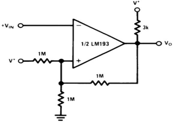
- Assume the input voltage at the non-inverting pin is less than the reference voltage, and the output is thus high.
- V* is the reference input voltage that generates a constant bias at the non-inverting input. Because the output is high due to the pull-up resistor, a current path is created through the feedback resistor, slightly increasing the reference voltage.
- When the input voltage exceeds the reference voltage, the output becomes low. This should not affect the reference voltage, but because there is a feedback resistor, the reference voltage drops slightly below the nominal value because the feedback and the lower reference resistor are now in parallel concerning the ground (since a low output short that terminal of the resistor to ground). Because the reference voltage has been reduced, there is no longer the possibility of a small change in input causing multiple transitions – in other words, there is no longer a dead zone.
- The input must now cross the new lower threshold to cause the output to go high. When the output is crossed, the circuit is ‘reset’ to its initial configuration. The input must only cross the threshold once to result in a single clean transition. The circuit is now bistable, with two effective thresholds or states.
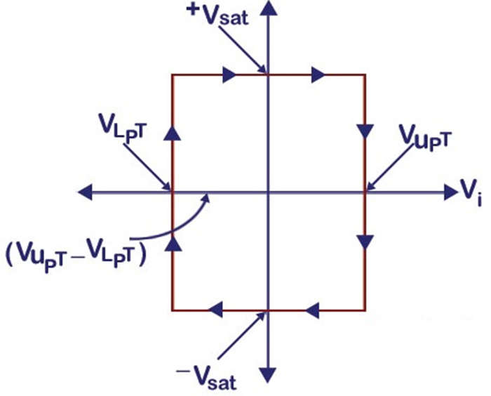
- This can be illustrated with a graph:
- The non-inverting comparator operates similarly in that the output changes the configuration of a resistor network to change the threshold to prevent unwanted oscillations or noise.
Analysis
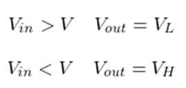
- Let’s look at how this circuit works now through the circuit’s mathematical analysis. The voltage at point A is V, and the applied voltage (input voltage) is Vin.
- If the applied voltage Vin is greater than V, the circuit’s output is low. If the applied voltage Vin is less than V, the circuit’s output will be high.
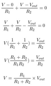
- Now compute the V equation,
- Applying Kirchhoff’s Current Law (KCL),
- Let us now assume that the Schmitt trigger output is high. In this situation,
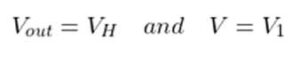
- So, from the above equation;
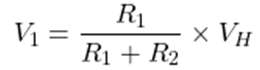
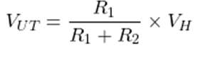
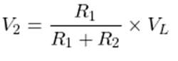
- When the input signal is greater than V1, the Schmitt trigger’s output becomes low. As a result, V1 is an upper threshold voltage (VUT).
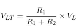
- Until the input signal is less than V, the output will remain low. When the Schmitt trigger output is low in this condition,
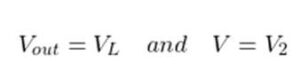
- The output is now held high until the input signal is less than V2. As a result, V2 is referred to as a lower threshold voltage (VLT).
Applications of Op-Amp Based Schmitt Trigger
- The conversion of Sine waves to Square waves is an important application of Schmitt Trigger.
- They can be used to remove chatter from Comparators (a phenomenon where multiple output transitions are produced due to the swinging of input signal through the threshold region).
- They can also function as simple ON/OFF switches (for example, temperature-based switches).
- They must be used in the switch de-boun Acer circuit to clean up or speed up a noisy otherwise slow input requirement.
- These are typically used in signal conditioning applications to remove noise from digital circuits.
- These are used to implement relaxation oscillators for negative response closed loop designs.