Introduction
The term thyristor refers to a semiconductor device that belongs to a family of solid-state switching components. A thyristor is a four-layer, three-junction device (J1, J2, J3) made of alternating P-type and N-type semiconductor materials. It has three terminals: anode, cathode, and gate.
When the anode of a thyristor is made positive with respect to the cathode and a gate signal is applied between the gate and cathode terminals, the device acts as a bistable switch and begins to conduct current.
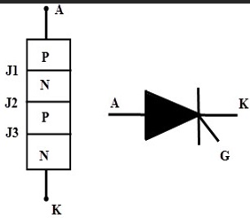
Symbol and Basic Construction of SCR
An SCR (Silicon Controlled Rectifier) consists of four semiconductor layers forming PNPN structure with three junctions. The device remains in the off state until a triggering signal is applied to the gate terminal.
What is SCR Triggering?
Triggering is the process of turning on a device from its off state. In the case of a thyristor, triggering refers to the process of turning the SCR ON. The SCR is turned on by increasing the anode current beyond a specific value. There are several methods of triggering a thyristor:
1. Voltage Triggering
In this method, the applied forward voltage is gradually increased beyond a point known as the forward breakover voltage (VBO), with the gate terminal open. However, this method is not preferred because it requires a high voltage and current during activation, which can result in power loss and possible device damage.
2. Thermal Triggering
When the temperature of the thyristor increases, the number of electron-hole pairs also rises, causing leakage currents to increase. This regenerative effect can lead to accidental triggering. Because it may cause thermal runaway, this method is not desirable and should be avoided.
3. Light Triggering
In this method, light rays are directed onto the thyristor’s junctions, increasing the number of charge carriers (electron-hole pairs) and turning the device ON. This technique is used in Light Activated SCRs (LASCRs).
4. dv/dt Triggering
If the rate of rise of voltage (dv/dt) across the anode and cathode is too high, the resulting capacitive charging current can be sufficient to turn on the thyristor. Since excessive dv/dt can damage the device, additional protection circuits are often used to limit voltage rise rates.
5. Gate Triggering
This is the most widely used method due to its simplicity and controllability. A gate signal is applied to the thyristor when it is forward biased. Once the gate current initiates conduction, the device continues to conduct even if the gate signal is removed, due to internal regenerative action within the SCR.
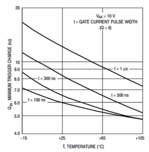
Effect of Temperature
As temperature increases, the amount of gate charge required to trigger the SCR decreases. This occurs because the lifetime of minority carriers increases with temperature, leading to less recombination loss.
Three types of charges are involved in gate triggering:
- Qr: Charge lost due to recombination.
- Qdr: Charge drained through the built-in gate-cathode shunt resistance.
- Qtr: Net charge required for triggering.
All three are temperature-sensitive. While Qdr remains mostly constant, Qr and Qtr decrease with rising temperature, reducing the total gate charge required to turn on the device.
As temperature rises, the minimum gate trigger charge decreases approximately exponentially. Experimental data (e.g., for MCR729 SCR) shows a slower rate of decrease at higher temperatures. The reduction is more prominent at high pulse widths where recombination charge is more significant.
Effect of Blocking Voltage
An SCR operates in avalanche mode during turn-on due to carrier multiplication in the middle collector junction. The multiplication factor (M) can be defined by the empirical relation:
M = (1 - V/VB)-n
Where:
- M: Multiplication factor
- V: Voltage across the middle collector junction (blocking voltage)
- VB: Breakdown voltage of the collector junction
- n: A positive constant
As the blocking voltage (V) increases, the multiplication factor (M) also increases, enhancing current amplification. Consequently, the minimum gate trigger charge slightly decreases with increasing blocking voltage. Experimental results confirm this effect for devices such as the MCR729 SCR.
Effect of Gate Circuit
For the SCR to turn on, the overall amplification factor must exceed unity. If some gate current is drained due to low gate impedance, turn-on characteristics are affected. A higher gate impedance results in a lower gate trigger charge.
At low gate current (near the threshold), gate impedance has minimal effect. However, when the SCR is overdriven for faster switching, gate impedance becomes a more significant factor in determining trigger charge requirements.
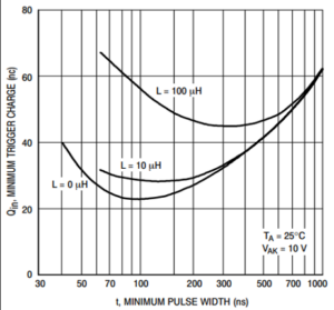
Effect of Inductive Load
When an SCR drives an inductive load, the rate of change of anode current (di/dt) slows down. As a result, the required trigger charge increases with inductance. While the inductive load has little effect on DC or long-pulse triggering, it significantly impacts short-pulse triggering.
This occurs because, with short pulses, the gate signal may end before the anode current reaches the sustaining level necessary to keep the SCR in conduction mode. Therefore, higher trigger charge or pulse width is required for reliable operation with inductive loads.
Conclusion
The Thyristor SCR Firing and Trigger Circuit plays a critical role in controlling power electronic systems. By understanding the effects of temperature, blocking voltage, gate circuit impedance, and inductive load, engineers can design efficient and reliable SCR triggering systems for applications such as motor control, rectifiers, and power converters.