- The 74HC157, also known as the 74HCT157, is a high-speed Si-gate CMOS device that is pin compatible with Low-power Schottky TTL.
- The 74HC/HCT157 is commonly used to transfer data from two groups of registers to four common output buses. The state of the common data select input (S) determines which register the data comes from. It can also be used to generate functions. The device can generate any four of the 16 different functions of two variables with one variable in common, making it useful for implementing highly irregular logic. The 74HC/HCT157 is a logic implementation of a 4-pole, 2-position switch, with the position determined by the logic levels applied to S.
- The 74HC157 is a two-input (2:1) multiplexer integrated circuit. It contains four similar multiplexers, hence the name Quad package 2-Input Multiplexer. which selects four bits of data from two sources using a common Select input (S). The Enable input (E) is turned off. When (E) is high, all of the outputs (1Y-4Y) in the 158, the inverting type, is forced high, and all of the outputs (1Y-4Y) in the 157, the non-inverting type, are forced low, regardless of all other input conditions.
Working
What is a Multiplexer and how does it work?
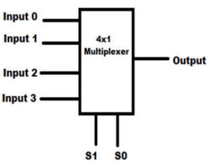
- A multiplexer (or mux; also spelled multiplexer) is a device in electronics that selects between several analogs or digital input signals and forwards the selected input to a single output line. A separate set of digital inputs known as select lines controls the selection. A multiplexer with 2n inputs has n select lines that determine which input line is sent to the output.
- Instead of having one device per input signal, a multiplexer allows several input signals to share one device or resource, such as one analog-to-digital converter or one communications transmission medium. Multiplexers can also be used to implement multiple variable Boolean functions.

ADVERTISEMENT
- A multiplexer is useful for transmitting a large amount of data over a network in a short period and with limited bandwidth. Multiplexers that are built from transistors and relays are termed analog multiplexers which are used in analog applications and Multiplexers that are built from the logic gate are termed digital multiplexers which are used in digital applications.
- The multiplexer functions similarly to a switch with multiple inputs and a single output. At any given time, the output is connected to only one of the n data inputs. As a result, the multiplexer is many to one device that functions as the digital equivalent of an analog selector switch.
Pin Configuration
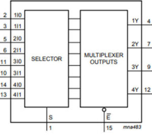
- The pin diagram of 74HC157 Multiplexer IC is shown below in fig.1 and logics operational diagram is shown below in fig.2.
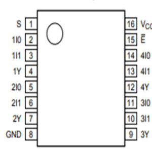
| Pin No. | Pin Name | Description |
|---|---|---|
| 1 | Line Select(S) | The select pin selects one of the two input lines and gives it to the output line. |
| 2,5,11,14 | Input A | This is the first input line of the 2:1 Multiplexer. |
| 3,6,10,13 | Input B | This is the second input line of the 2:1 Multiplexer. |
| 4,7,9,12 | Output Y | This is the output line pin of the Multiplexer. |
| 8 | Ground | Connected to the ground of the system. |
| 15 | Enable (E) | Active low pin. Grounded for normal operation. |
| 16 | VCC | This pin powers the IC, typically +5V is used. |