• Home
  • About Us
  • Contact Us
Semiconductor for You
"
  • Home
  • Semiconductor News
  • Technology
    • Automotive
    • Consumer Electronics
    • IoT
    • Lighting
    • Power Management
    • Wireless
    • Personal Electronics
    • Hardware & Software
    • Research
    • Medical Electronics
    • Embedded Design
    • Aerospace & Defence
    • Artificial Intelligence
  • DIY Projects
  • Market
  • Industries
    • Renesas Electronics
  • Knowledge Base
  • Events
  • Tools
    • Resistor Color Code Calculator
No Result
View All Result
Semiconductor for You
No Result
View All Result
Home Knowledge Base

What is an Regenerative Receiver : Regen Radio

Nikita Bisen by Nikita Bisen
September 13, 2022
in Knowledge Base
0
ADVERTISEMENT

The regenerative receiver or regen radio provides a significant increase in gain and selectivity over the standard tuned radio frequency receiver.

  • It was invented in 1912 and patented in 1914 by American electrical engineer Edwin Armstrong. It was used between 1915 and World War II.
  • It is an amplifier circuit that employs positive feedback (also known as regeneration or reaction).
  • The amplifying device output is applied back to its input to add to the input signal, increasing the amplification.
  • For example, is the Schmitt trigger (which is also known as a regenerative comparator), but the most common use of the term is in RF amplifiers, and especially regenerative receivers, to greatly increase the gain of a single amplifier stage.
Fig. 1: Schematic of a characteristic regenerative radio receiver
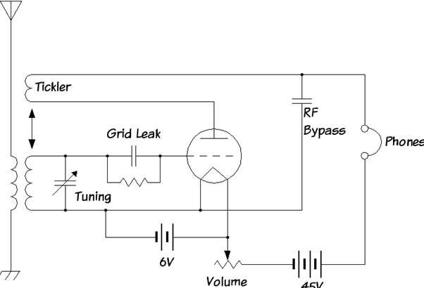
  • The above diagram shows the schematic of the regenerative receiver.
  • The antenna gives the incoming RF signal and passed through a tunable BPF tank so it selects the desired channel.
  • Then this signal is then amplified by a triode or other device used in the regen receiver.
  • The amplified output signal is then given back into the resonant tank via the tickler coil where it is once again filtered by the tank and amplified by the tube.
  • The two effects of positive feedback–increased gain and bandwidth sharpening–are easily understood through a simplified analysis of the system.
Fig. 2: The effect of successive passes through the positive feedback loop on the transfer function of the receiver
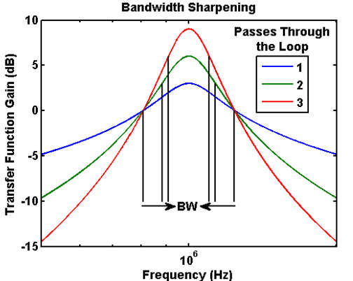
  • The above figure shows the series of transfer functions represented in Fig. 2. Without positive feedback the circuit has the transfer function represented by the blue curve.
  • It allows the multiple time the signal is passed through the circuit with positive feedback and each pass increase the selectivity of the filter and the passband gain of the receiver.
  • Both the passband gain and the selectivity of the circuit system are extremely high but remain finite as a result of diminishing returns in the feedback loop.
Fig. 3: Applying even order distortion to the AM signal and low pass filtering the result effectively demodulates the desired signal
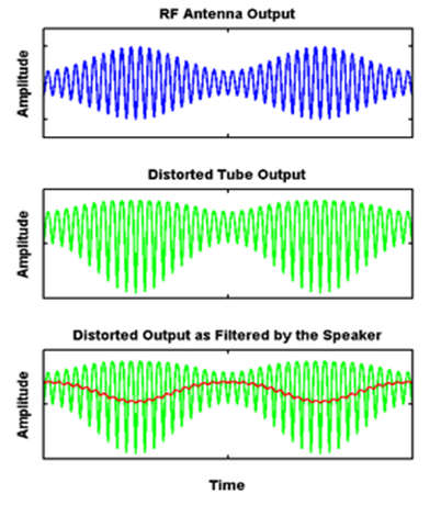
  • The single vacuum tube of the nonlinear response is also used to demodulate the signal. Fig. 3 demonstrates this effect.
  • The original amplitude modulated signal is passed through the distorting nonlinearity of the tube, which applies different levels of distortion to positive and negative swinging signals.
  • Sending this distorted signal through a simple LPF is enough to recover the desired signal.

Advantages of Regenerative Receiver

  • Provides high performance for a few components.
  • High levels of gain resulting from regeneration.
  • High Q from use of regeneration.

Disadvantages of Regenerative Receiver

  • Requires more operator skill than other types of receiver.
  • Can radiate when the detector is in oscillator mode, or close to it.
  • Can only receive AM, Morse, & SSB – modes like FM are not viable.
Content Protection by DMCA.com
Nikita Bisen

Nikita Bisen

Browse by Category

  • Aerospace and Defence
  • Articles
  • Automotive
  • Consumer-Electronics
  • Hardware & Software
  • Interview
  • IoT
  • Knowledge Base
  • Lighting
  • Market
  • personal-electronics
  • Power Management
  • Research
  • Semiconductor Events
  • Semiconductor News
  • Technology
  • Wireless
Semiconductor for You

Semiconductor For You is a resource hub for electronics engineers and industrialist. With its blend of
technology features, news and new product information, Semiconductor For You keeps designers and
managers up to date with the fastest moving industry in the world.

Follow Us

Browse by Category

  • Aerospace and Defence
  • Articles
  • Automotive
  • Consumer-Electronics
  • Hardware & Software
  • Interview
  • IoT
  • Knowledge Base
  • Lighting
  • Market
  • personal-electronics
  • Power Management
  • Research
  • Semiconductor Events
  • Semiconductor News
  • Technology
  • Wireless

Recent News

AI-Ready MCUs and the Road Ahead

AI-Ready MCUs and the Road Ahead

May 14, 2025
Renesas Collaborates with Indian Government to Empower Startups and Boost Semiconductor Innovation

Renesas Collaborates with Indian Government to Empower Startups and Boost Semiconductor Innovation

May 13, 2025
  • About
  • Advertise
  • Privacy & Policy
  • Contact

© 2022 Semiconductor For You

No Result
View All Result
  • Home
  • Semiconductor News
  • Technology
    • IoT
    • Wireless
    • Power Management
    • Automotive
    • Hardware & Software
  • Market
  • Knowledge Base
  • Tools
    • Resistor Color Code Calculator

© 2022 Semiconductor For You