Introduction
The insulation resistance (IR) test is one of the most commonly used methods to determine the reliability of insulation in electrical systems. It is widely performed on cables, transformers, motors, switchgear, and electrical installations. Although it is not a new testing method, the insulation resistance test remains essential in both manufacturing and maintenance processes. Customers often specify minimum insulation resistance values per unit length, making this test a standard quality requirement. Factors such as installation method, type of application, and operating environment significantly influence insulation resistance values.
What Is Insulation Resistance Testing?
An insulation resistance test is used to measure the resistance between two points that are separated by electrical insulation. This test evaluates how effectively the insulation restricts the flow of electric current. The insulation

Insulation Resistance Test
resistance test is also known as the Megger test. It helps determine the condition and quality of insulation both during manufacturing and while equipment is in service.
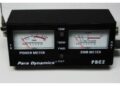
Insulation Resistance Test Equipment (Megger)
A megger, also called a megohmmeter, is used to measure insulation resistance. It is a high-resistance ohmmeter equipped with a DC generator or high-voltage battery.
The megger has three terminals:
- Line terminal (L)
- Earth terminal (E)
- Guard terminal (G)
The insulation resistance is commonly measured between the Line (L) and Earth (E) terminals. The Guard (G) terminal is used when surface leakage resistance must be excluded from the measurement.
Insulation Resistance Test Circuit Diagram
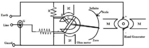
Insulation Resistance Testing Circuit
The megger generates a high DC voltage that causes a small leakage current to flow through the insulation under test. The resistance value is then displayed on the instrument’s scale.
Working Principle of Insulation Resistance Test
When a high DC voltage is applied across the insulation, a very small current flows through or across the insulating material. According to Ohm’s law, the insulation resistance is calculated from the applied voltage and the resulting current. Higher resistance values indicate good insulation, while lower values suggest insulation deterioration or damage.
Procedure for Insulation Resistance Test
- Ensure the megger shows infinity when not connected and zero when terminals are shorted.
- Disconnect the cable or equipment from all power sources.
- Discharge any stored energy by properly earthing the equipment.
- Ensure the equipment is at normal operating temperature.
- Keep the conductors separated from each other.
- Connect the megger terminals to the conductors under test.
- Operate the megger and note the resistance reading.
If the reading is very high or infinite, the insulation is considered to be in good condition.
Advantages of Insulation Resistance Test
- Determines the effectiveness of insulation in restricting current flow
- Helps prevent electric shocks and short circuits
- Ensures electrical safety and reliability
- Used as a quality control test during manufacturing
- Detects insulation deterioration at an early stage
Applications of Insulation Resistance Test
- Testing cables and wiring systems
- Transformers, motors, and generators
- Switchgear and control panels
- Electrical installations in buildings
- Industrial plants and power systems
- Preventive maintenance and safety inspections
Conclusion
The insulation resistance test is a vital diagnostic and safety test used to evaluate the condition of insulation in electrical systems. By identifying insulation weaknesses early, this test helps prevent equipment failure, short circuits, and electrical hazards.