- A Darlington pair NPN transistor is the TIP122. It performs the same functions as a standard NPN transistor, but because it contains a Darlington pair, it has a good 5A collector current rating and a gain of roughly 1000. It can drive high loads because it can handle roughly 100V across its collector-emitter. The internal circuit diagram of this transistor, which displays the Darlington pair inside of it, is shown below.
- As you can see, this TO-220 package has two transistors, with the emitter of the first transistor connected to the base of the second and the collector of both transistors coupled to form a Darlington pair. This raises the transistor’s current gain and current rating.
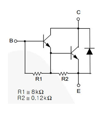
- A highly well-liked Darlington NPN transistor is the TIP122, which has a high current gain and high current. The term “Darlington” refers to a situation in which two transistors are available in a single pack to increase the gain at the o/p. This transistor can be produced for switch-like and amplification-related uses.
How to use TIP122?
- Despite having a high collector current and current gain, TIP only has a low emitter-base voltage (VBE) of 5V and a base current of 120mA, making it relatively easy to manage. I used the TIP122 to control a 48V motor with a continuous current of approximately 3A in the circuit shown below.
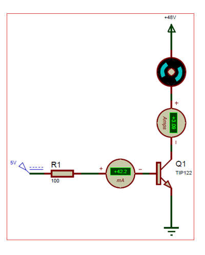
- Our load only uses 3A of the transistor’s 5A continuous collector current, which is acceptable. The highest base current is around 120mA, but I’ve reduced it to 42mA by using a high-value 100-ohm resistor. If your requirement for collector current is minimal, you can even use a 1K resistor.
- Make sure your motor doesn’t use more than 8A of the peak (pulse) current of this transistor. This is only a model circuit diagram that illustrates how this transistor operates; it cannot be utilized in actual operation. You can therefore similarly manage your load.
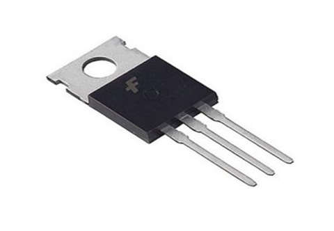
Pin Configuration
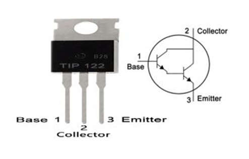
- A TIP122 transistor has the following pin arrangement. This transistor has three pins; the purpose of each pin is covered below.
- Pin1 (Base): This pin controls the transistor biasing.
- Pin2 (Collector): The flow of current will be there throughout this pin
- Pin3 (Emitter): This pin is used to drain the current
Applications of TIP122 Transistor
- Based on its characteristics, this transistor can be utilized as a switch in many electronic circuits to drive various loads below 5A. This transistor is mostly used in circuits for power supplies, motor drives, and battery chargers.
- This transistor also functions as an audio pre-amplifier and amplifier. 5V DC is the transistor EB voltage. To regulate loads that draw less than 5A, this transistor can be linked to the microcontroller’s o/p & logic devices.
- This transistor is employed anywhere strong amplification is required as well as for managing high current loads. A microcontroller, often known as a logic device, is used to control this transistor simply, but care must be taken to ensure that it can handle 120mA.
- A logic device may simply control this transistor to switch maximum power loads or to magnify the maximum current. Therefore, this transistor is the ideal option for your needs.