A Waveguide:
- Microwaves propagate through microwave circuits, components, and devices, which act as a part of Microwave transmission lines, broadly called Waveguides.
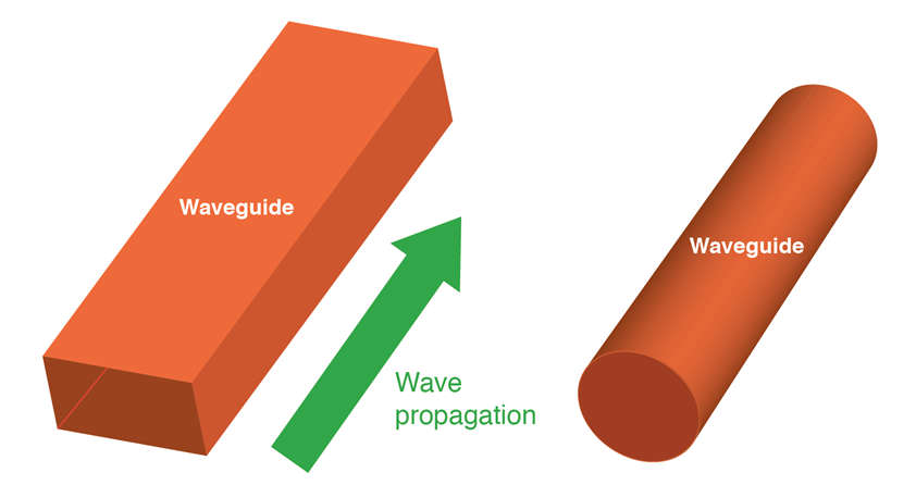
- A waveguide is a hollow metallic tube of a uniform cross-section for transmitting electromagnetic waves by successive reflections from the inner walls of the tube is called as a Waveguide.
- A waveguide is an electromagnetic feed line used in microwave communications, broadcasting, and radar installations.
- A waveguide consists of a rectangular or cylindrical metal tube or pipe. The electromagnetic field propagates lengthwise. Waveguides are most often used with horn antennas and dish antennas.
- An electromagnetic field can propagate along a waveguide in various ways.
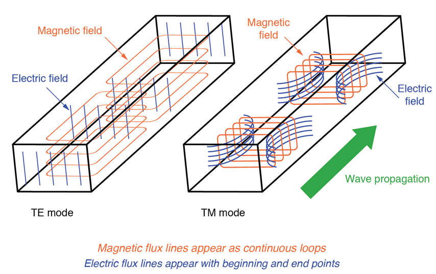
There are Two Common Modes
- Transverse-magnetic (TM)
- Transverse-electric (TE)
- In TM mode, the magnetic lines of flux are perpendicular to the axis of the waveguide.
- In TE mode, the electric lines of flux are perpendicular to the axis of the waveguide.
- A waveguide must have a certain minimum diameter relative to the wavelength of the signal, to work for the waveguide to work properly.
- If the waveguide is too narrow or the frequency is too low (the wavelength is too long), the electromagnetic fields cannot propagate.
Characteristics of Waveguide
- The tube wall provides distributed inductance.
- The space between the tube walls provides distributed capacitance.
- These are bulky, heavy, and expensive.
Types of Waveguide
There are five types of waveguides.
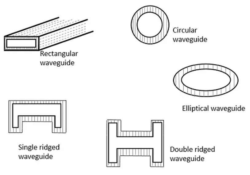
1. Rectangular Waveguide
- Rectangular waveguides Both TE and TM modes can be supported by these waveguides. The electric field is transverse to the direction of propagation in TE modes. The magnetic field is transverse to the direction of propagation in TM modes.
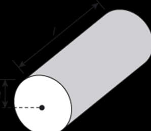
2. Circular Waveguide
- They tend to twist the waves as they travel through them and are used with rotating antennas in radars.
3. Elliptical Waveguide
- An elliptical shape is often preferred in flexible waveguides. These waveguides will be required whenever its section is capable of movement, such as bending, stretching, or twisting.
- A waveguide with conducting ridges protruding into the center of the waveguide from the top wall or bottom wall or both walls is called a Ridged Waveguide.
- The ridges are parallel to the short wall of the waveguide.
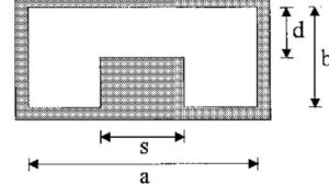
4. Single Ridged Waveguides
- A rectangular waveguide with a single protruding ridge from the top or bottom wall is called a Single Ridged waveguide.
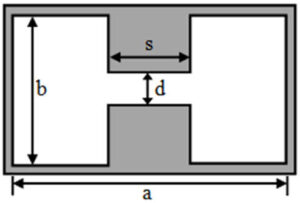
5. Double Ridged Waveguides
- A rectangular waveguide with a ridge from the top and bottom wall is called a Double Ridged Waveguide.
Mode of Propagation
A mode of propagation is nothing but a distinct field pattern. There are four different mode categories.

TEM Mode or Principal Mode (Ez = 0 and Hz = 0)
- In this mode, both the E and H fields are transverse to the direction of wave propagation, and this is known as the transverse electromagnetic (TEM) mode. Due to Ez = 0 and Hz = 0 in this mode, all field components are reduced to zero, so that there is no field component along the direction of propagation. Thus, from the result, a rectangular waveguide cannot support the TEM mode.

TE mode (Ez= 0 and Hz≠ 0)
- In this mode Ez = 0, at all points within the waveguide. This means that there is no electric field vector component along the direction of propagation, and the magnetic field vector is along the direction of propagation.

TM modes (Ez≠ 0 and Hz= 0)
- In this mode Hz = 0 at all points within the waveguide. This means that there is no magnetic field vector component along the direction of propagation, and the electric field vector is parallel to the long axis.

HE modes (Ez≠ 0 and Hz= 0)
- In this case, neither E nor H field is transverse to the direction of wave propagation, and they are known as hybrid modes.
Parameters of a Waveguide
Cut-off wavelength
- It is the maximum signal wavelength of the transmitted signal that can be propagated within the waveguide without any attenuation. It is denoted by λc.
Group velocity
- Group velocity is the velocity with which the wave propagates inside the waveguide.
- If the transmitted carrier is modulated, then the velocity of the modulation envelope is somewhat less as compared to the carrier signal.
- This velocity of the envelope is termed group velocity. It is represented by Vg.
Phase velocity
- It is the velocity with which the transmitted wave changes its phase during propagation. It is the velocity of a particular phase of the propagating wave. It is denoted by Vp.
Wave Impedance
- It is also known as the characteristic impedance.
- It is defined as the ratio of the transverse electric field to that of the transverse magnetic field during wave propagation at any point inside the waveguide.
- It is denoted by Zg.