
Introduction
An Analog to Digital Converter (ADC) is an essential feature in modern microcontrollers, enabling them to interpret and process real-world analog signals such as temperature, voltage, or light intensity. This article explains how the ADC module works in a PIC microcontroller and how analog signals are converted into digital values for further processing.
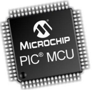
What is a PIC Microcontroller?
PIC stands for Programmable Interface Controller. These microcontrollers can be preprogrammed to perform a wide range of tasks, from controlling an assembly line to managing home automation systems. They are widely used in alarm systems, embedded control systems, and various consumer electronics.
Among the different families of PIC microcontrollers, the GENIE series is known for its versatility and ease of programming. These can be programmed and simulated using Circuit Wizard software. PIC microcontrollers are available both as pre-built circuits and DIY kits, making them affordable and user-friendly for students and professionals alike.
Understanding Analog to Digital Conversion
Embedded systems primarily operate with digital data. However, most sensors and real-world inputs produce analog signals. To process these analog inputs, the microcontroller requires an Analog to Digital Converter (ADC) that transforms continuous voltage levels into discrete digital values.
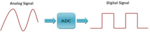
For instance, in a PIC microcontroller project, an external analog signal (ranging from 0V to 5V) can be read, converted into a digital equivalent, and displayed on an LCD screen. This enables the system to monitor varying input voltages accurately.
Resolution of an ADC
The most critical characteristic of an ADC is its resolution—the number of discrete steps it divides the reference voltage into. Common ADC resolutions include 8-bit, 10-bit, and 12-bit.
- An 8-bit ADC divides the 0–5V input range into 256 levels. Each step represents approximately 19 mV (5V ÷ 256).
- A 10-bit ADC divides the same range into 1024 levels, providing finer accuracy of about 4.88 mV (5V ÷ 1024).
Thus, higher resolution results in more precise measurement of analog signals. The ADC in most PIC microcontrollers is a 10-bit converter, offering a good balance between speed and accuracy. According to Microchip, the ADC module in PIC microcontrollers can achieve a sampling rate of up to 100,000 samples per second.
ADC Module in PIC Microcontroller
Most PIC microcontrollers include a built-in ADC module. Devices with 28 pins typically have five analog input channels, while 40-pin devices may feature up to eight inputs. The ADC module converts an analog voltage signal into a corresponding 10-bit digital number.
The module also supports software-selectable voltage references for both high and low inputs, which can be connected to VSS, VDD, RA2, or RA3. These reference voltages determine the conversion range of the ADC.
By configuring the ADCON1 register, users can adjust reference voltages and define which pins act as analog or digital inputs. This flexibility allows for accurate measurement and display of analog values using LEDs or an LCD.
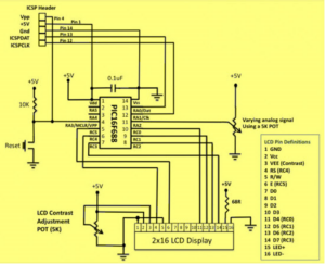
Circuit Diagram of ADC in PIC Microcontroller
The basic circuit for the 10-bit ADC in a PIC microcontroller involves connecting a test voltage input to one of the analog input pins, typically AN2/RA2. A 5kΩ potentiometer is used to vary the input voltage between 0V and 5V. The reference voltage is usually derived from the power supply.
As the input voltage changes, the PIC’s ADC module converts it into a digital value, which can then be displayed on an LCD screen. This demonstrates how analog signals from sensors or potentiometers can be digitized and processed in real-time.
Conclusion
The ADC module in PIC microcontrollers is a powerful tool for interfacing with the analog world. It enables devices to measure physical quantities accurately and convert them into digital data that can be displayed or processed. Understanding and utilizing the ADC effectively is crucial for anyone designing embedded systems and automation projects using PIC microcontrollers.